
Technical data


Electrical Considerations
7
Electrical Considerations
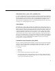
Signal Termination
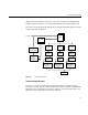
The video data and control signals are transmitted from MC100E151 registers clocked by
the rising edge of pixel clock. The data signals must be terminated at the receiver with
the Thevinin-equivalent network shown in Figure 1-3. The DVP interface is a
point-to-point interface.
Note: Do not bus the signals. The cable has a 110-ohm characteristic impedance, and is
designed to be used with PC boards of 55-ohm characteristic impedance traces. Be sure
that all data signal pairs are of equal length, and as short as possible. Terminations
should be at the end-of-line, within 300 mils of the differential receiver inputs.
Figure 1-3 Recommended Termination of Differential Signals
Pixel Clock Rate Limits
DVP pixel clock can be programmed to operate between 2.5 MHz and 175 MHz, allowing
the DVP interface to support video formats between 2.5 and 175 Mpix/sec. (The DVP
board was designed for a maximum operating rate of 230 Mpixels/sec, but is not
guaranteed beyond 175 Mpix/sec in the Onyx InfiniteReality graphics system. Contact
Silicon Graphics if your application requirements exceed 175 Mpixels/sec.)
55
121
55