
Technical data


4
Chapter 1: DVP Specifications
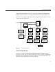
Note: The connector pin-out depends on which end of the cable it is connected. (See
Table 1-1 and Table 1-2 for the transmit and receive pinouts.)
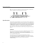
Figure 1-2 Connector Physical Footprint
Signal Descriptions
The DVP interface features differential, 5-volt positive-ECL (5V-PECL) signalling. This
document uses the UNIX
®
syntactic convention of “curly braces” to show alternatives for
the signal polarity. This convention allows a single name to refer to both of the signals in
the differential pair, yet makes it obvious that there are two signals. (In actual schematics,
each differential pair signal has its own name with the polarity specified and the curly
braces omitted. For example, this document might describe a differential pair as
FOO_{H,L}, whereas actual schematics would show the pair of signals as FOO_H and
FOO_L.)
Video Data
There are 72 video data signals, which comprise 36 differential signal pairs. These are
split into three color components of 12 bits each: (RED_OUT_{H,L}[11:0],
GREEN_OUT_{H,L}[11:0], BLUE_OUT_{H,L}[11:0]). The InfiniteReality DVP interface
does not include the Alpha channel.
This document uses the following video data signal naming convention:
ColorComponentName_OUT_SignalPolarity[SignificantBit]. The last digit of the signal
name indicates the binary significance of the digital color component. For example, the
most significant bit of the positive-logic version green component is
GREEN_OUT_H[11].
1
2
49
50
51
52
99
100
MTG1
MTG2
Board edge
Board edge