
Technical data


Physical Characteristics
3
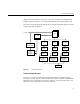
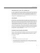
digital video channel similar to the other analog video channels of the InfiniteReality
graphics subsystem. Figure 1-1 shows the block diagram of the DVP daughterboard.
The other end of the external DVP cable plugs into customer-designed equipment, which
complies with this specification.
Figure 1-1 DVP Block Diagram
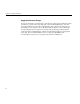
Connector Specification
The receiver connector must be mechanically and electrically compatible with the
following connector: 3M part number 102A0-5242VC. There should be no built-in EMI
filtering because of the deleterious effect it would have on electrical performance. (See
Figure 1-2 for the component-side connector footprint.)
Localbus
VOC
(1 x ICS1522)Video PLL
Localbus I/F,
&
Mode Register
2:1 Mux
ttl-ecl
buffer
ecl shift
register
single-ended to
differential ecl
register
12
2:1 Mux
Connector
ttl-ecl
buffer
ecl shift
register
single-ended to
differential ecl
register
12
2:1 Mux
ttl-ecl
buffer
ecl shift
register
single-ended to
differential ecl
register
12
Clock
Generator &
Distributer