InfiniteReality™ Digital Video Port (DVP) Specification Document Number 007-3594-001
CONTRIBUTORS Written by David Warren, David Naegle, and Bruce Miles Illustrated by David Warren, David Naegle, and Cheri Brown Production by Michael Dixon Engineering contributions by Gordon Elder, David Warren, and David Naegle St. Peter’s Basilica image courtesy of of ENEL SpA and InfoByte SpA . Disk Thrower image courtesy of Xavier Berenguer, Animatic © 1997, Silicon Graphics, Inc.
instruction manual, may cause harmful interference to radio communications. Operation of this equipment in a residential area is likely to cause harmful interference in which case the user will be required to correct the interference at his own expense. Attention This product requires the use of external shielded cables in order to maintain compliance pursuant to Part 15 of the FCC Rules.
TUV R geprufte Sicherheit NRTL/C InfiniteReality™ Digital Video Port (DVP) Specification Document Number 007-3594-001
Contents List of Figures vii List of Tables ix About This Guide xi Conventions xi 1.
List of Figures Figure 1-1 Figure 1-2 Figure 1-3 Figure 1-4 Figure 1-5 DVP Block Diagram 3 Connector Physical Footprint 4 Recommended Termination of Different Signals Recommended Receiver Design 9 DVP Clock and Data Timing 10 7 vii
List of Tables Table 1-1 Table 1-2 DVP Transmitter (DVIO) Pinouts DVP Transmitter (DVIO) Pinouts 13 18 ix
About This Guide This guide describes the Digital Video Port (DVP) specifications. This information is written for Silicon Graphics® customers who are connecting specialized, high-resolution, digital imagery equipment to Onyx® deskside and rackmount systems. It contains one chapter: “DVP Specifications,” which provides the Digital Video Port specifications.
Chapter 1 1. DVP Specifications This chapter describes the DVP Specifications.
Chapter 1: DVP Specifications negligible in most applications. Digital video data on the DVP appears in the same frame as video on the analog channels. Physical Characteristics DVP Cable Components The DVP physical interface consists of a single, 100-conductor, 110-ohm cable organized as 45 differential signal pairs.
Physical Characteristics digital video channel similar to the other analog video channels of the InfiniteReality graphics subsystem. Figure 1-1 shows the block diagram of the DVP daughterboard. The other end of the external DVP cable plugs into customer-designed equipment, which complies with this specification.
Chapter 1: DVP Specifications Note: The connector pin-out depends on which end of the cable it is connected. (See Table 1-1 and Table 1-2 for the transmit and receive pinouts.) Board edge MTG1 52 51 2 1 Figure 1-2 Board edge 100 99 50 49 MTG2 Connector Physical Footprint Signal Descriptions The DVP interface features differential, 5-volt positive-ECL (5V-PECL) signalling. This document uses the UNIX® syntactic convention of “curly braces” to show alternatives for the signal polarity.
Signal Descriptions Video Clocks (CLK_2_{H,L}, CLK_2_QUAD_{H,L}) To control in-flight skew between clock and data caused by nonuniform group delay in the cable, it is important to carefully match the spectral characteristics of the clocks to the data transmitted on the DVP interface. This is accomplished by transmitting an in-phase and a quadrature-phase version of the pixel clock, divided by 2. (See Figure 1-4 for Silicon Graphics recommendations for recovering a full-speed pixel clock on the receiver.
Chapter 1: DVP Specifications • VOC_SWAP can also be programmed to be continuously HI or LOW. For more information, contact Silicon Graphics technical support or your local service provider. Other Signals (HMUX_SEL{1,0}_{H,L}) These signals are reserved for future development of the DVP interface. The current implementation always asserts these two signal pairs as LOW.
Electrical Considerations Electrical Considerations Signal Termination The video data and control signals are transmitted from MC100E151 registers clocked by the rising edge of pixel clock. The data signals must be terminated at the receiver with the Thevinin-equivalent network shown in Figure 1-3. The DVP interface is a point-to-point interface. Note: Do not bus the signals.
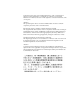
Chapter 1: DVP Specifications Suggested Receiver Design Over most of the DVP’s operating range, clock skew is an important consideration in the transmission of pixel clock to the video option board and distributing it to the video option board. Because of its wide operating limits, phase-locked-loop techniques are unsuitable for receiving the clocks on the DVP interface.
Electrical Considerations MC100E452 ts = 150psec th = 250psec DVP Differential Data (typ) On Receiver Board: SY100EL16A 175/355 psec Keep all clock line lengths equal from E111 to all receiving registers. SY100EL07 140/415 psec Clock/2 SY100EL16 175/355 psec Clock/2_quad 1:9 Differential clock driver MC100E111 430/630 psec Note: allow 200psec (1.12 in.) each for the wires between the EL16A and the EL07, and for the wires between the EL07 and the E111. Allow 750psec (4.2 in.
Chapter 1: DVP Specifications pixel clk CLK_2_H CLK_2_QUAD_H recovered clk DVP video data A B C D W X Y Z CBLANK_H CBLANK leads data by three clocks. Figure 1-5 DVP Clock and Data Timing Electromagnetic Interference Precautions When the external DVP interface cable is not in place, the data drivers are powered down to save power and minimize EMI interference to other equipment. 5V-PECL signals have lower emissions than CMOS or TTL signals.
16-Bit Luminance The branch circuit wiring should be provided with an insulated grounding conductor that is identical in size, insulation material, and thickness to the earthed and unearthed branch-circuit supply conductors. The grounding conductor should be green, with or without one or more yellow stripes. This grounding or earthing conductor should be connected to earth at the service equipment or, if supplied by a separately derived system, at the supply transformer or motor-generated set.
Chapter 1: DVP Specifications must not be exceeded; swap-rates must match across channels) apply to DVP as they do to the analog video channels. Genlocking DG4 to External Sources The equipment connected to the DVP interface is expected to be slaved to the video timing of the DG4 board via the DVP signals FRAME_{H,L}, VSYNC_{H,L}, CSYNC_{H,L}, and CBLANK_{H,L}. Operating the receiver in slave mode results in the absolute minimum video data latency.
Signal Lists Signal Lists DVIO Connector Signals Table 1-1 shows the signals on the DVIO connector. Table 1-1 DVP Transmitter (DVIO) Pinouts Pin No.
Chapter 1: DVP Specifications Table 1-1 (continued) 14 DVP Transmitter (DVIO) Pinouts Pin No.
Signal Lists Table 1-1 (continued) DVP Transmitter (DVIO) Pinouts Pin No.
Chapter 1: DVP Specifications Table 1-1 (continued) 16 DVP Transmitter (DVIO) Pinouts Pin No.
Signal Lists Table 1-1 (continued) DVP Transmitter (DVIO) Pinouts Pin No.
Chapter 1: DVP Specifications Receiver Connector Signals Because of the construction of the external cable, the pinout is reversed on the receiver connector. Table 1-2 shows the pinout of the receiver connector. Table 1-2 18 DVP Receiver Pinouts Pin No.
Signal Lists Table 1-2 (continued) DVP Receiver Pinouts Pin No.
Chapter 1: DVP Specifications Table 1-2 (continued) 20 DVP Receiver Pinouts Pin No.
Signal Lists Table 1-2 (continued) DVP Receiver Pinouts Pin No.
Chapter 1: DVP Specifications Table 1-2 (continued) 22 DVP Receiver Pinouts Pin No.
Tell Us About This Manual As a user of Silicon Graphics products, you can help us to better understand your needs and to improve the quality of our documentation. Any information that you provide will be useful.