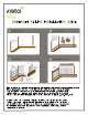
vista SOMERSET RAILING INSTALLATION GUIDE Bose herons pb d itn Randi install sis bis chats pts Eat IRs its ; = IRE Dejected] fon tabs eo als Debian rik unpleasing This document Is co detailed step—by—step installation guide for the Somerset railing system. These instructions may not cover dll scenarios that may arise. Before beginning your Installation toke time to read dll instructions thoroughly. A fundamental understanding of carpentry and ¢ basic knowledge of power tools is essential.
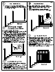
MD Step 1 Install Newel Posts A) Set posts to accommodate required tall lengths. See detail 1-3, 1-4 for post attachment methods. Considering your tall height, posts may be trimmed to c desirable post height. fe Diagram 1-A A) Measure the distance between posts. B) Mark the required length on the rails keeping preinstalled holes centered between the marks. C) Subtract 1/8" (3mm) cot each end for hanger brackets.
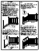
STAIR INSTALLATION A) Lay the bottom ROFL across the nosing of the stairs keeping the preinstalled holes centered between the posts. Mark the points were It Intersects the posts. See Detail 6-A B) Subtract 1/8” (3mm) at each end of roils for hanger brackets. C) Trim the bottom real with a miter saw. D) Respect this process for the top tall ensuring that the preinstalled holes cre facing downward. E) For bottom rails, place rockets over ends of rail with preinstalled holes ond open end of bracket facing up.
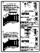
Step 10 Instilling The Cap All A) Measure the distance between the posts. B)} Mark the required length on the cep tall and trim with a miter sow. C) Apply exterior type Il glue to the top rail. Cap rel is fitted on top ond nailed, 2 %" (63mm) galvanized balls @ 12" (600mm). See detail 1-2 Fasten the cep roll to the post using 2—4#8 x 2" (50mm) screws Instilled at a 45 degree angle. See detail 1-1 and 1-2. — \ Milagros 11 a Step 11 Construction And Finishing Tips A) Installation of screws in riles should be
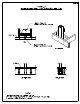
Page 4 Detail 1-3 Exterior Connection: Post screwed to rim joist x 76mm (3") Stainless Steel Screws Per Side Rim Joist. A i 4-10 x 76mm (3") Stainless Steel Screws Per Side Taxonomy tic Decking Front Elevation Side Elevation Detail 1-3 Exterior Connection: Post Clenched To Rim Joist 1) Decking is omitted from plan view end the trigonometric view for clarity. 2) Softeners shall be resistant to corrosion.
vista For Technical support please call 1-800-667-8247 Instructions are also available on our website www.vistarcilings.com Tool List Hammer Ratchet Wrench Tape Measure Wood Chisel Miter saw Level Clamps Hand Drill Stainless Screws #8 x 2” (50mm) Drill Bit Size g&" (3.