
Product Manual


VISIONXLIGHTING.COM
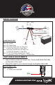
WIRING DIAGRAM
(R1)
(S1) (W3)
(W1)
(W2)
*To Light *To Light
(C2)(C1)
(R2)
(P1)
(W4)
(-)
(-)
(+)
(+)
COMPONENTS KEY
Part (R1 & R2) Relay
Part (S1) Switch
Part (P1) Switch Plug
Part (W1 & W3) Power Wire for Relay Coil
a. 9-32V DC Positive (=) Input Wire
Part (W2 & W4) Ground Wire for Relay Coil
a. 9-32V DC Negative (-) Input Wire
Part (C1 & C2) Deutsch Connectors for Lights
a. Attached to 9-32V DC Positive (+) Power Wires
LIGHT ANGLE ADJUSTMENTS
1. Use a 10mm socket to loosen the 1 Hex head bolts Part (B2)
on the side of the light.
2. Adjust the light to your desired angle and tighten Bolt (B2).
ADJUSTMENT KEY
Part (B2) Bolt
a. 10mm Hex Head Bolt
(B2)
1.94”/49mm