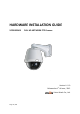
HARDWARE INSTALLATION GUIDE VPD200SM2i FULL HD NETWORK PTZ Camera Version 1. 0. 0 Released on 1 of June., 2012 st Vision Hitech Co., Ltd.
PRECAUTIONS By selecting this product, you have decided to use a professional device that guarantees highest quality and reliability. We would like to thank you very much for your confidence and kindly ask you to read the following instructions carefully before installation and operation in order to take full advantage of all quality features regarding this product.
Table of content Hardware Installation Guide 1. Precautions ---------------------------------------------------------------------------------------------------- 4 2. Limitation of liability ---------------------------------------------------------------------------------------- 4 3. Disclaimer of warranty ------------------------------------------------------------------------------------- 4 4.
1. Precautions Please read the manual carefully before the installation in order to set up the camera correctly and to obtain the best picture quality. Please keep the manual in good condition for your future reference and service application. Installation and services should be only carried out by an authorized personnel according to local safety regulations.
(2) Personal injury or any damage caused by inappropriate use or negligent operation of the user; (3) Unauthorized disassemble, repair or modification of the product by the user; (4) Inconvenience or any loss arising when images are not displayed, due to any reason or cause including any failure or problem of the product; (5) Any problem, consequential inconvenience, or loss or damage, arising out of the system combined by the devices of third party.
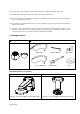
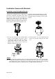
5. Cable Connection • Dome Cover Do not detach protection vinyl from dome cover before finishing all installation process to protect dome cover from scratches or dust. • DIP Switch Sets up camera ID and protocol. • Drop Prevention Spring This part keeps the camera from dropping during installation and maintenance. After install the Bracket, please, hang the spring to the drop prevention hook of main body as shown in picture for further tasks.
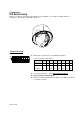
6. Installation DIP Switch Setup When you control the camera through RS-485, before installation, you should set the DIP switches to configure the camera ID, communication protocol. Camera ID setup ON ON ID numbers of camera are set up with binary numbers..
Communication Protocol Setup ON ON 1 2 3 4 Select the appropriate Protocol with DIP switch combination. Switch State P0 (Pin 1) P1 (Pin 2) P2 (Pin 3) Protocol/Baud rate OFF ON OFF ON OFF OFF ON ON Otherwise OFF OFF OFF OFF PELCO-D, 2400 bps PELCO-D, 9600 bps PELCO-P, 4800 bps PELCO-P, 9600 bps Reserved If you want to control using DVR or P/T controller, their protocol must be identical to camera. Otherwise, you can not control the camera.
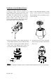
Installation Camera with Brackets Installation using Ceiling Mount Bracket ① Remove the ceiling tile from the ceiling and cut a hole whose diameter is 30~40mm on the ceiling tile to pass the wire(s) and cable(s) through to the upside of the ceiling. (In case of the wiring and cabling through the mounting surface only) Then prepare the ceiling mount bracket. Pull the wire(s) for the system as below.
Installation using Wall Mount Bracket ① Make a hole whose diameter is 30~40mm on the mounting surface to pass the wire(s) and cable(s) through the mounting surface. (In case of the wiring and cabling through the mounting surface only) Then prepare the wall mount bracket. Pull the wire(s) and cable(s) for the system as below. Attach the wall mount bracket to the mounting surface.
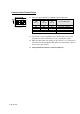
Wiring/Cabling & Connecting Port Description Main Cable Port Pin Number (RJ45) Connector / Wire Color Signal 1 Black RS485 + 2 Brown RS485 3 Red DC 12V 4 Orange Ground 5 Yellow OUT COM (Relay Output Common) 6 Green OUT 2 (Relay Output 2) 7 Blue OUT 1 (Relay Output 1) 8 Violet IN COM (Sensor Input Common) 9 Gray IN 1 (Sensor Input 1) 10 White IN 2 (Sensor Input 2) Port Pin Number Connector/ Wire Color Signal 1 RCA (Yellow) Audio IN Audio Cable 2 3 Page 11 /
Connecting Power 1. Carefully check the voltage and current capacity of the rated power. The rated power is indicated in the back of main unit. 2. After confirming the power source, connect power adaptor and connect the 12V DC connector to the system For the DC input models, be careful with the polarity of DC power. The system should be permanently damaged by wrong DC input. In case that the length of the power wire is very long, there may be voltage drop and the system may not work properly.
RS-485 of VPD200SM2i can be connected to external equipment such as PT receiver etc. PC client can send PT commands to the external equipment via the serial port. When a decoder system instead of PC client is connected to VPD200SM2i, the serial port and that of the decoder system works in pass-through mode. That is, data from at one port is delivered to the other port, vice versa Connecting Sensor and Alarm Connect sensor and alarm devices to corresponding terminals accordingly.
7. Dimension (mm) 8. Specification 8.1. VPD200SM2i Specification Model Image sensor Day & Night 1/2.8" SONY progressive sc an CMOS image sensor for excellent image quality Auto/Color/BW(ICR) Environment Optical Zoom Digital Zoom Lens OUTDOOR(IP66) 20X 12X 20x AF zoom ( f4.7~94mm (F1.6~F3.5)) Min. illumination / Light sensitivity (Lux) 0.5 Lux (B/W) / F1.
Audio Network Audio streaming Compression Sample Rate Data Rate Audio input Audio output Security Two-way, full duplex G.