
Datasheet

VT4045BP-M3
www.vishay.com
Vishay General Semiconductor
Revision: 05-Nov-13
2
Document Number: 89441
For technical questions within your region: DiodesAmericas@vishay.com
, DiodesAsia@vishay.com, DiodesEurope@vishay.com
THIS DOCUMENT IS SUBJECT TO CHANGE WITHOUT NOTICE. THE PRODUCTS DESCRIBED HEREIN AND THIS DOCUMENT
ARE SUBJECT TO SPECIFIC DISCLAIMERS, SET FORTH AT www.vishay.com/doc?91000
Notes
(1)
Pulse test: 300 μs pulse width, 1 % duty cycle
(2)
Pulse test: Pulse width 40 ms
RATINGS AND CHARACTERISTICS CURVES (T
A
= 25 °C unless otherwise noted)
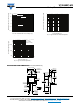
Fig. 1 - Maximum Forward Current Derating Curve
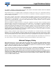
Fig. 2 - Typical Instantaneous Forward Characteristics
ELECTRICAL CHARACTERISTICS (T
A
= 25 °C unless otherwise noted)
PARAMETER TEST CONDITIONS SYMBOL TYP. MAX. UNIT
Instantaneous forward voltage
I
F
= 5 A
T
A
= 25 °C
V
F
(1)
0.41 -
V
I
F
= 20 A 0.50 -
I
F
= 40 A 0.57 0.67
I
F
= 5 A
T
A
= 125 °C
0.28 -
I
F
= 20 A 0.41 -
I
F
= 40 A 0.51 0.63
Reverse current V
R
= 45 V
T
A
= 25 °C
I
R
(2)
- 3000 μA
T
A
= 125 °C 29 85 mA
THERMAL CHARACTERISTICS (T
A
= 25 °C unless otherwise noted)
PARAMETER SYMBOL VT4045BP UNIT
Typical thermal resistance R
JC
0.8 °C/W
ORDERING INFORMATION (Example)
PACKAGE PREFERRED P/N UNIT WEIGHT (g) PACKAGE CODE BASE QUANTITY DELIVERY MODE
TO-220AC VT4045BP-M3/4W 1.87 4W 50/tube Tube
0
5
10
15
20
25
30
35
40
45
0 25 50 75 100 125 150 175 200
DC Forward Current (A)
Case Temperature (°C)
DC Forward Current at
Thermal Equilibrium
0.1
1
10
100
0.0 0.1 0.2 0.3 0.4 0.5 0.6 0.7
Instantaneous Forward Current (A)
Instantaneous Forward Voltage (V)
T
A
= 150 °C
T
A
= 100 °C
T
A
= 25 °C
T
A
= 125 °C