
Datasheet


VS-HFA15TB60SPbF, VS-HFA15TB60-1PbF
www.vishay.com
Vishay Semiconductors
Revision: 10-Jun-11
1
Document Number: 94054
For technical questions within your region: DiodesAmericas@vishay.com
, DiodesAsia@vishay.com, DiodesEurope@vishay.com
THIS DOCUMENT IS SUBJECT TO CHANGE WITHOUT NOTICE. THE PRODUCTS DESCRIBED HEREIN AND THIS DOCUMENT
ARE SUBJECT TO SPECIFIC DISCLAIMERS, SET FORTH AT www.vishay.com/doc?91000
HEXFRED
®
,
Ultrafast Soft Recovery Diode, 15 A
FEATURES
• Ultrafast and ultrasoft recovery
• Very low I
RRM
and Q
rr
• Meets MSL level 1, per J-STD-020, LF maximum
peak of 260 °C
• Halogen-free according to IEC61249-2-21
definition
• Compliant to RoHS Directive 2002/95/EC
• Designed and qualified for industrial level
• AEC-Q101 qualified
BENEFITS
• Reduced RFI and EMI
• Reduced power loss in diode and switching transistor
• Higher frequency operation
• Reduced snubbing
• Reduced parts count
DESCRIPTION
VS-HFA15TB60SPbF, VS-HFA15TB60-1PbF is a state of
the art ultrafast recovery diode. Employing the latest in
epitaxial construction and advanced processing techniques
it features a superb combination of characteristics which
result in performance which is unsurpassed by any rectifier
previously available. With basic ratings of 600 V and
15 A continuous current, the VS-HFA15TB60SPbF,
VS-HFA15TB60-1PbF is especially well suited for use as the
companion diode for IGBTs and MOSFETs. In addition to
ultrafast recovery time, the HEXFRED
®
product line features
extremely low values of peak recovery current (I
RRM
) and
does not exhibit any tendency to “snap-off” during the t
b
portion of recovery. The HEXFRED features combine to offer
designers a rectifier with lower noise and significantly lower
switching losses in both the diode and the switching
transistor. These HEXFRED advantages can help to
significantly reduce snubbing, component count and
heatsink sizes. The HEXFRED VS-HFA15TB60SPbF,
VS-HFA15TB60-1PbF is ideally suited for applications in
power supplies and power conversion systems (such as
inverters), motor drives, and many other similar applications
where high speed, high efficiency is needed.
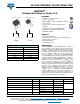
PRODUCT SUMMARY
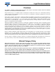
Package TO-263AB (D
2
PAK), TO-262AA
I
F(AV)
15 A
V
R
600 V
V
F
at I
F
1.7 V
t
rr
(typ.) 23 ns
T
J
max. 150 °C
Diode variation Single die
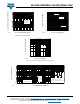
D
2
PAK
Base
cathode
Anode
1
3
2
N/C
TO-262
N/C
Anode
1
3
2
VS-HFA15 TB60SPbF VS-HFA15 TB60-1PbF
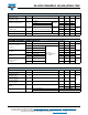
ABSOLUTE MAXIMUM RATINGS
PARAMETER SYMBOL TEST CONDITIONS VALUES UNITS
Cathode to anode voltage V
R
600 V
Maximum continuous forward current I
F
T
C
= 100 °C 15
ASingle pulse forward current I
FSM
150
Maximum repetitive forward current I
FRM
60
Maximum power dissipation P
D
T
C
= 25 °C 74
W
T
C
= 100 °C 29
Operating junction and storage temperature range T
J
, T
Stg
- 55 to + 150 °C