
Datasheet

www.vishay.com For technical questions within your region, please contact one of the following: Document Number: 93538
4 DiodesAmericas@vishay.com
, DiodesAsia@vishay.com, DiodesEurope@vishay.com Revision: 11-Mar-11
This datasheet is subject to change without notice.
THE PRODUCT DESCRIBED HEREIN AND THIS DATASHEET ARE SUBJECT TO SPECIFIC DISCLAIMERS, SET FORTH AT
www.vishay.com/doc?91000
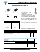
VS-ETU3006-M3, VS-ETU3006FP-M3
Vishay Semiconductors
Ultrafast Rectifier, 30 A FRED Pt
®
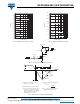
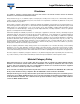
Fig. 5 - Maximum Thermal Impedance Z
thJC
Characteristics (FULL-PAK)
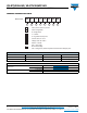
Fig. 6 - Maximum Allowable Case Temperature vs.
Average Forward Current
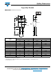
Fig. 7 - Maximum Allowable Case Temperature vs.
Average Forward Current (FULL-PAK)
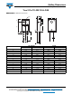
Fig. 8 - Forward Power Loss Characteristics
t1, Rectangular Pulse Duration (Seconds)
Thermal Impedance Z
thJC (°C/W)
1E-05 1E-04 1E-03 1E-02 1E-01 1E+00 1E+01 1E+02
0.1
1
10
Single Pulse
(Thermal Resistance)
D = 0.02
D = 0.05
D = 0.1
D = 0.2
D = 0.5
D = 0.01
Average Forward Current - IF
(AV)
(A)
Allowable Case Temperature (°C)
0 5 10 15 20 25 30 35
120
130
140
150
160
170
180
DC
Average Forward Current - I
F
(AV)
(A)
Allowable Case Temperature (°C)
0 5 10 15 20 25 30 35
20
40
60
80
100
120
140
160
180
DC
Average Forward Current - IF
(AV)
(A)
Average Power Loss ( Watts )
0 5 10 15 20 25 30 35 40 45
0
10
20
30
40
50
60
D = 0.01
D = 0.02
D = 0.05
D = 0.1
D = 0.2
D = 0.5
DC
RMS Limit