
Datasheet

VS-ETL0806-M3, VS-ETL0806FP-M3
www.vishay.com
Vishay Semiconductors
Revision: 16-Apr-14
4
Document Number: 93528
For technical questions within your region: DiodesAmericas@vishay.com
, DiodesAsia@vishay.com, DiodesEurope@vishay.com
THIS DOCUMENT IS SUBJECT TO CHANGE WITHOUT NOTICE. THE PRODUCTS DESCRIBED HEREIN AND THIS DOCUMENT
ARE SUBJECT TO SPECIFIC DISCLAIMERS, SET FORTH AT www.vishay.com/doc?91000
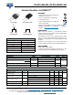
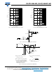
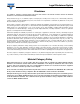
Fig. 5 - Maximum Thermal Impedance Z
thJC
Characteristics (FULL-PAK)
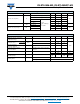
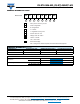
Fig. 6 - Maximum Allowable Case Temperature vs.
Average Forward Current
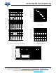
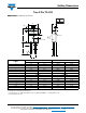
Fig. 7 - Maximum Allowable Case Temperature vs.
Average Forward Current (FULL-PAK)
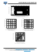
Fig. 8 - Forward Power Loss Characteristics
t
1
, Rectangular Pulse Duration (Seconds)
Thermal Impedance ZthJC (°C/W)
1E-05 1E-04 1E-03 1E-02 1E-01 1E+00 1E+01 1E+02
0.1
1
10
Single Pulse
(Thermal Resistance)
D = 0.02
D = 0.05
D = 0.1
D = 0.2
D = 0.5
D = 0.01
Average Forward Current - IF
(AV)
(A)
Allowable Case Temperature (°C)
0 2 4 6 8 10
140
150
160
170
180
DC
Average Forward Current - IF
(AV)
(A)
Allowable Case Temperature (°C)
0 2 4 6 8 1
0
80
100
120
140
160
180
DC
Average Forward Current - I
F
(AV)
(A)
Average Power Loss ( Watts )
024681012
0
2
4
6
8
10
12
D = 0.01
D = 0.02
D = 0.05
D = 0.1
D = 0.2
D = 0.5
DC
RMS Limit