
Datasheet

VS-8EWF02S-M3, VS-8EWF04S-M3, VS-8EWF06S-M3
www.vishay.com
Vishay Semiconductors
Revision: 18-Dec-13
3
Document Number: 93375
For technical questions within your region: DiodesAmericas@vishay.com
, DiodesAsia@vishay.com, DiodesEurope@vishay.com
THIS DOCUMENT IS SUBJECT TO CHANGE WITHOUT NOTICE. THE PRODUCTS DESCRIBED HEREIN AND THIS DOCUMENT
ARE SUBJECT TO SPECIFIC DISCLAIMERS, SET FORTH AT www.vishay.com/doc?91000
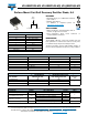
Fig. 1 - Current Rating Characteristics
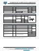
Fig. 2 - Current Rating Characteristics
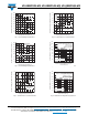
Fig. 3 - Forward Power Loss Characteristics
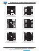
Fig. 4 - Forward Power Loss Characteristics
Fig. 5 - Maximum Non-Repetitive Surge Current
Fig. 6 - Maximum Non-Repetitive Surge Current
60
70
80
90
100
110
120
130
140
150
0123456789
30°
60°
90°
120°
180°
Maximum Allowable Case Temperature (°C)
Conduction Angle
Average Forward Current (A)
8EWF..S Serie s
R (DC) = 2.5 °C/ W
thJC
70
80
90
100
110
120
130
140
150
02468101214
DC
30°
60°
90°
120°
180°
Maximum Allowable Case Temperature (°C)
Conduction Period
Average Forward Current (A)
8EWF..S Se ries
R (DC) = 2.5 °C/ W
thJC
0
2
4
6
8
10
12
0123456789
RM S Li m i t
180°
120°
90°
60°
30°
Conduction Angle
Average Forward Current (A)
Maximum Average Forward Power Loss (W)
8EWF..S Se ries
T = 150°C
J
0
2
4
6
8
10
12
14
16
02468101214
DC
180°
120°
90°
60°
30°
RM S Li m i t
Conduction Period
Average Forward Current (A)
Maximum Average Forward Power Loss (W)
8 EW F. . S Se r i e s
T = 1 5 0° C
J
Number of Equal Amplitude Half Cycle
Current Pulses (N)
Peak Half Sine Wave
Forward Current (A)
1 10 100
30
40
50
60
70
80
90
100
110
120
130
140
VS-8EWF..S .. Series
At any rated load condition and with
rated Vrrm applied following surge.
Initial Tj = 150°C
at 60 Hz 0.0083s
at 50 Hz 0.0100s
0.01 0.1 1 10
10
30
50
70
90
110
130
150
170
Maximum non-repetitive surge current
versus pulse train duration.
Initial Tj = Tj max.
No voltage reapplied
Rated Vrrm reapplied
VS-8EWF..S .. Series
Pulse Train Duration (s)
Peak Half Sine Wave
Forward Current (A)