
Datasheet


VS-60.PF0.PbF Series, VS-60.PF0.-M3 Series
www.vishay.com
Vishay Semiconductors
Revision: 06-Feb-14
3
Document Number: 93710
For technical questions within your region: DiodesAmericas@vishay.com
, DiodesAsia@vishay.com, DiodesEurope@vishay.com
THIS DOCUMENT IS SUBJECT TO CHANGE WITHOUT NOTICE. THE PRODUCTS DESCRIBED HEREIN AND THIS DOCUMENT
ARE SUBJECT TO SPECIFIC DISCLAIMERS, SET FORTH AT www.vishay.com/doc?91000
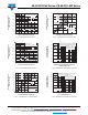
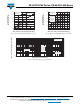
Fig. 1 - Current Rating Characteristics
Fig. 2 - Current Rating Characteristics
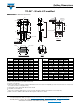
Fig. 3 - Forward Power Loss Characteristics
Fig. 4 - Forward Power Loss Characteristics
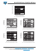
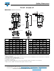
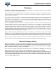
Fig. 5 - Maximum Non-Repetitive Surge Current
Fig. 6 - Maximum Non-Repetitive Surge Current
150
0
Maximum Allowable Case
Temperature (°C)
Average Forward Current (A)
10
100
20 70
120
130
110
30
50
140
40
90
60
60.PF.. Series
R
thJC
(DC) = 0.4 K/W
Conduction angle
30°
60°
90°
120°
180°
Ø
150
040
Maximum Allowable Case
Temperature (°C)
Average Forward Current (A)
80
110
100
120
20
130
140
100
90
60
30°
60°
90°
120°
180°
DC
Ø
Conduction period
60.PF.. Series
R
thJC
(DC) = 0.4 K/W
10
0
90
0
Maximum Average Forward
Power Loss (W)
Average Forward Current (A)
50
40
70
50
30
20 3010
20
60
40
180°
120°
90°
60°
30°
Conduction angle
60.PF.. Series
T
J
= 150 °C
RMS limit
60
70
80
Ø
0
140
0
Maximum Average Forward
Power Loss (W)
Average Forward Current (A)
60
100
20
40
100
20
60
120
80
8040
Ø
Conduction period
60.PF.. Series
T
J
= 150 °C
180°
120°
90°
60°
30°
DC
RMS limit
800
1 10 100
Peak Half Sine Wave
Forward Current (A)
Number of Equal Amplitude Half Cycle
Current Pulses (N)
400
200
300
500
700
600
At any rated load condition and with
rated V
RRM
applied following surge.
Initial T
J
= 175 °C
at 60 Hz 0.0083 s
at 50 Hz 0.0100 s
60.PF.. Series
200
0.01 0.1
Peak Half Sine Wave
Forward Current (A)
Pulse Train Duration (s)
500
100
300
400
700
900
1
600
800
Maximum non-repetitive surge current
versus pulse train duration.
Initial T
J
= 195 °C
No voltage reapplied
Rated V
RRM
reapplied
60.PF.. Series