
Datasheet


VS-40EPS..PbF Series, VS-40EPS..-M3 Series
www.vishay.com
Vishay Semiconductors
Revision: 06-Feb-14
3
Document Number: 94343
For technical questions within your region: DiodesAmericas@vishay.com
, DiodesAsia@vishay.com, DiodesEurope@vishay.com
THIS DOCUMENT IS SUBJECT TO CHANGE WITHOUT NOTICE. THE PRODUCTS DESCRIBED HEREIN AND THIS DOCUMENT
ARE SUBJECT TO SPECIFIC DISCLAIMERS, SET FORTH AT www.vishay.com/doc?91000
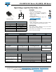
Fig. 3 - Forward Power Loss Characteristics
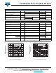
Fig. 4 - Forward Power Loss Characteristics
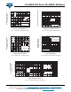
Fig. 5 - Forward Voltage Drop Chacteristics
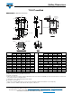
Fig. 6 - Maximum Non-Repetitive Surge Current
Fig. 7 - Thermal Impedance Z
thJC
Characteristics
5
0
10
15
20
25
35
30
40
45
50
55
60
Maximum Average Forward
Power Loss (W)
V
FM
- Forward Voltage Drop (V)
5
40353025201510
0
RMS limit
180°
120°
90°
60°
30°
VS-40EPS.. Series
T
J
= 150 °C
Conduction angle
Ø
40
30
50
60
70
80
20
10
0
Maximum Average Forward
Power Loss (W)
Average Forward Current (A)
70605040302010
0
DC
180°
120°
90°
60°
30°
RMS limit
VS-40EPS.. Series
T
J
= 150°C
Ø
Conduction period
1
100
10
1000
Instantaneous Forward Current (A)
Instantaneous Forward Voltage (V)
0.5 2.0 2.51.51.0
3.0
0
T
J
= 25 °C
T
J
= 150 °C
VS-40EPS.. Series
400
450
500
350
300
250
200
150
100
Peak Half Sine Wave
Forward Current (A)
Pulse Train Duration (S)
0.1 1.00.01
Maximum non-repetitive surge current
VS-40EPS.. Series
Initial T
J
= 150 °C
No voltage reapplied
Rated V
RRM
reapplied
versus pulse train duration.
0.01
0.1
1
0.001 0.01 0.1 1
Square Wave Pulse Duration (s)
Z
thJC
- Transient Thermal
Impedance (°C/W)
Steady state value:
(DC operation)
Single pulse
VS-40EPS.. Series
D = 0.50
D = 0.33
D = 0.25
D = 0.17
D = 0.08