
Datasheet

www.vishay.com For technical questions within your region, please contact one of the following: Document Number: 94200
4 DiodesAmericas@vishay.com
, DiodesAsia@vishay.com, DiodesEurope@vishay.com Revision: 14-Jan-11
VS-30WQ10FNPbF
Vishay Semiconductors
Schottky Rectifier, 3.5 A
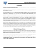
Fig. 5 - Maximum Allowable Case Temperature vs.
Average Forward Current
Fig. 6 - Forward Power Loss Characteristics
Fig. 7 - Maximum Non-Repetitive Surge Current
Note
(1)
Formula used: T
C
= T
J
- (Pd + Pd
REV
) x R
thJC
;
Pd = Forward power loss = I
F(AV)
x V
FM
at (I
F(AV)
/D) (see fig. 6);
Pd
REV
= Inverse power loss = V
R1
x I
R
(1 - D); I
R
at V
R1
= 80 % rated V
R
115
120
125
130
135
140
145
150
155
Allowable Case Temperature (°C)
I
F (AV)
- Average Forward Current (A)
0.5 1.0 1.5 2.0 2.5 3.0 3.5 4.0 4.5 5.0 5.50
DC
See note (1)
Square wave (D = 0.50)
80 % rated V
R
applied
0
0.5
1.0
1.5
2.0
2.5
3.0
3.5
Average Power Loss (W)
I
F (AV)
- Average Forward Current (A)
234501
DC
RMS Limit
D = 0.20
D = 0.25
D = 0.33
D = 0.50
D = 0.75
10
100
1000
I
FSM
- Non- Repetitive Surge Current (A)
t
p
- Square Wave Pulse Duration (µs)
100 1000 10 00010
At any rated load condition
and with rated V
RRM
applied
following surge