
Datasheet


www.vishay.com For technical questions, contact: diodestech@vishay.com
Document Number: 94168
4 Revision: 12-Mar-10
VS-20TQ035SPbF, VS-20TQ040SPbF, VS-20TQ045SPbF
Vishay High Power Products
Schottky Rectifier, 20 A
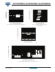
Fig. 5 - Maximum Allowable Case Temperature vs.
Average Forward Current
Fig. 6 - Forward Power Loss Characteristics
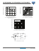
Fig. 7 - Maximum Non-Repetitive Surge Current
Fig. 8 - Unclamped Inductive Test Circuit
115
145
135
125
155
Allowable Case Temperature (°C)
I
F(AV)
- Average Forward Current (A)
52025
30
100
15
20TQ
R
thJC
(DC) = 1.50 °C/W
DC
0
8
6
4
2
18
16
14
12
10
Average Power Loss (W)
I
F(AV)
- Average Forward Current (A)
515 302010025
D = 0.08
D = 0.17
D = 0.25
D = 0.33
D = 0.50
RMS limit
DC
100
1000
10 000
I
FSM
- Non-Repetitive Surge Current (A)
t
p
- Square Wave Pulse Duration (µs)
100
10 000
100010
At any rated load condition
and with rated V
RRM
applied
following surge
Current
monitor
High-speed
switch
D.U.T.
R
g
= 25 Ω
+
Freewheel
diode
V
d
= 25 V
L
IRFP460
40HFL40S02