
Datasheet

VS-6FL(R), VS-12FL(R), VS-16FL(R) Series
www.vishay.com
Vishay Semiconductors
Revision: 21-Jan-14
3
Document Number: 93138
For technical questions within your region: DiodesAmericas@vishay.com
, DiodesAsia@vishay.com, DiodesEurope@vishay.com
THIS DOCUMENT IS SUBJECT TO CHANGE WITHOUT NOTICE. THE PRODUCTS DESCRIBED HEREIN AND THIS DOCUMENT
ARE SUBJECT TO SPECIFIC DISCLAIMERS, SET FORTH AT www.vishay.com/doc?91000
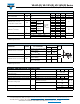
Note
• The table above shows the increment of thermal resistance R
thJC
when devices operate at different conduction angles than DC
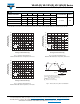
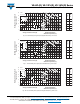
Fig. 1 - Average Forward Current vs.
Maximum Allowable Case Temperature, 6FL Series
Fig. 2 - Average Forward Current vs.
Maximum Allowable Case Temperature, 12FL Series
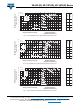
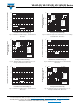
Fig. 3 - Average Forward Current vs.
Maximum Allowable Case Temperature, 16FL Series
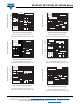
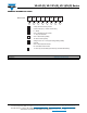
Fig. 4 - Reverse Recovery Time Test Waveform
R
thJC
CONDUCTION
CONDUCTION ANGLE
6FL.. 12FL.. 16FL.. 6FL.. 12FL.. 16FL..
TEST CONDITIONS UNITS
SINUSOIDAL CONDUCTION RECTANGULAR CONDUCTION
180° 0.58 0.46 0.37 0.33 0.26 0.21
T
J
= 150 °C K/W
120° 0.60 0.48 0.39 0.58 0.46 0.37
60° 1.28 1.02 0.82 1.28 1.02 0.82
30° 2.20 1.76 1.41 2.20 1.76 1.41
Average Forward Current (A)
Maximum Allowable
Case Temperature (°C)
160
150
140
130
120
110
100
90
80
70
60
0123 4 567 8 910
DC
180 °C
120 °C
60 °C
180 °C
Average Forward Current (A)
Maximum Allowable
Case Temperature (°C)
160
150
140
130
120
110
100
90
80
70
60
02 4 6 8 10 12 14 16 18 20
DC
180 °C
180 °C
120 °C
60 °C
Average Forward Current (A)
Maximum Allowable
Case Temperature (°C)
160
150
140
130
120
110
100
90
80
70
60
010515202530
DC
180 °C
180 °C
120 °C
60 °C
I
F
, I
FM
- Peak forward current prior to commutation
-dI
F
/dt - Rate of fall of forward current
I
RM(REC)
- Peak reverse recovery current
t
rr
- Reverse recovery time
Q
rr
- Reverse recovered charge
%I
RM(REC)
I
RM(REC)
Q
rr
t
rr
t
I
F
I
I
FM
dI
F
dt