
Datasheet

VS-12F(R) Series
www.vishay.com
Vishay Semiconductors
Revision: 28-Jan-14
3
Document Number: 93487
For technical questions within your region: DiodesAmericas@vishay.com
, DiodesAsia@vishay.com, DiodesEurope@vishay.com
THIS DOCUMENT IS SUBJECT TO CHANGE WITHOUT NOTICE. THE PRODUCTS DESCRIBED HEREIN AND THIS DOCUMENT
ARE SUBJECT TO SPECIFIC DISCLAIMERS, SET FORTH AT www.vishay.com/doc?91000
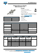
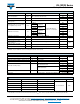
Fig. 1 - Current Ratings Characteristics Fig. 2 - Current Ratings Characteristics
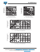
Fig. 3 - Forward Power Loss Characteristics
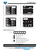
Fig. 4 - Forward Power Loss Characteristics
140
150
160
170
180
0 2 4 6 8 10 12 14
30°
60°
90°
120°
180°
Maximum Allowable
Case Temperature (°C)
Conduction Angle
Average Forward Current (A)
12F(R) Series
R (DC) = 2.0 K/W
thJC
130
140
150
160
170
180
0 4 8 12 16 20
DC
30°
60°
90°
120°
180°
Maximum Allowable
Case Temperature (°C)
Conduction Period
Average Forward Current (A)
12F(R) Series
R (DC) = 2.0 K/W
thJC
25 50 75 100
Maximum Allowable Ambient Temperature (°C)
R
=
8
K
/
W
-
D
e
l
t
a
R
t
h
S
A
6
K
/
W
1
0
K
/
W
1
2
K
/
W
1
5
K
/
W
2
0
K
/
W
3
0
K
/
W
0
2
4
6
8
10
12
14
Average Forward Current (A)
RMS Limit
Maximum Average Forward
Power Loss (W)
Conduction Angle
180°
120°
90°
60°
30°
12F(R) Series
T = 175°C
J
0 2 4 6 8 10 12 14
25 50 75 100
Maximum Allowable Ambient Temperature (°C)
R
=
6
K
/
W
-
D
e
l
t
a
R
t
h
S
A
8
K
/
W
1
0
K
/
W
1
2
K
/
W
1
5
K
/
W
2
0
K
/
W
3
0
K
/
W
0
4
8
12
16
20
0 4 8 12 16 20
DC
180°
120°
90°
60°
30°
Average Forward Current (A)
RMS Limit
Maximum Average Forward
Power Loss (W)
Conduction Period
12F(R) Series
T = 175°C
J