
Datasheet


VO615A
www.vishay.com
Vishay Semiconductors
Rev. 2.3, 08-Feb-17
3
Document Number: 81753
For technical questions, contact: optocoupleranswers@vishay.com
THIS DOCUMENT IS SUBJECT TO CHANGE WITHOUT NOTICE. THE PRODUCTS DESCRIBED HEREIN AND THIS DOCUMENT
ARE SUBJECT TO SPECIFIC DISCLAIMERS, SET FORTH AT www.vishay.com/doc?91000
Note
• According to DIN EN 60747-5-5 (VDE 0884), § 7.4.3.8.2 (see Fig. 2). This optocoupler is suitable for safe electrical isolation only within the
safety ratings. Compliance with the safety ratings shall be ensured by means of suitable protective circuits
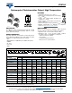
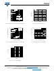
CURRENT TRANSFER RATIO (T
amb
= 25 °C, unless otherwise specified)
PARAMETER TEST CONDITION PART SYMBOL MIN. TYP. MAX. UNIT
I
C
/I
F
V
CE
= 5 V, I
F
= 1 mA
VO615A-1 CTR 13 30 - %
VO615A-2 CTR 22 45 - %
VO615A-3 CTR 34 70 - %
VO615A-4 CTR 56 90 - %
V
CE
= 5 V, I
F
= 5 mA
VO615A CTR 50 - 600 %
VO615A-5 CTR 50 - 150 %
VO615A-6 CTR 100 - 300 %
VO615A-7 CTR 80 - 160 %
VO615A-8 CTR 130 - 260 %
VO615A-9 CTR 200 - 400 %
V
CE
= 5 V, I
F
= 10 mA
VO615A-1 CTR 40 - 80 %
VO615A-2 CTR 63 - 125 %
VO615A-3 CTR 100 - 200 %
VO615A-4 CTR 160 - 320 %
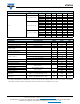
SAFETY AND INSULATION RATED PARAMETERS
PARAMETER TEST CONDITION SYMBOL VALUE UNIT
Climatic classification According to IEC 68 part 1 55 / 110 / 21
Pollution degree According to DIN VDE 0109 2
Comparative tracking index Insulation group IIIa CTI 250
Maximum rated withstanding
isolation voltage
According to UL1577, t = 1 min V
ISO
5000 V
AC
Maximum transient isolation voltage According to DIN EN 60747-5-5 V
IOTM
6000 V
peak
Maximum repetitive peak
isolation voltage
According to DIN EN 60747-5-5 V
IORM
850 V
peak
Isolation resistance
T
amb
= 25 °C, V
IO
= 500 V R
IO
≥ 10
12
Ω
T
amb
= 100 °C, V
IO
= 500 V R
IO
≥ 10
11
Ω
T
amb
= T
S
, V
IO
= 500 V R
IO
≥ 10
9
Ω
Output safety power P
SO
265 mW
Input safety current I
SI
130 mA
Input safety temperature T
S
150 °C
Creepage distance
DIP-4; SMD-4, option 7;
SMD-4, option 9
≥ 7.6 mm
Clearance distance ≥ 7.6 mm
Creepage distance
DIP-4, 400 mil, option 6;
SMD-4, option 8
≥ 8.0 mm
Clearance distance ≥ 8.0 mm
Insulation thickness DTI ≥ 0.4 mm
Input to output test voltage,
method B
V
IORM
x 1.875 = V
PR
, 100 % production test
with t
M
= 1 s, partial discharge < 5 pC
V
PR
1600 V
peak
Input to output test voltage,
method A
V
IORM
x 1.6 = V
PR
, 100 % sample test
with t
M
= 10 s, partial discharge < 5 pC
V
PR
1360 V
peak