
Datasheet

VLMRGB343..
www.vishay.com
Vishay Semiconductors
Rev. 1.7, 18-Sep-14
5
Document Number: 81742
For technical questions, contact: LED@vishay.com
THIS DOCUMENT IS SUBJECT TO CHANGE WITHOUT NOTICE. THE PRODUCTS DESCRIBED HEREIN AND THIS DOCUMENT
ARE SUBJECT TO SPECIFIC DISCLAIMERS, SET FORTH AT www.vishay.com/doc?91000
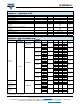
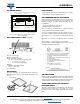
TAPING DIMENSIONS in millimeters
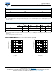
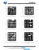
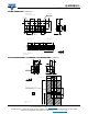
PACKAGE DIMENSIONS / SOLDERING PADS DIMENSIONS in millimeters
20819
Taping and orientation
Reels come in quantity of 2050 units
Cathode marking
960 mm min. for Ø 330 reel200 mm min. for Ø 330 reel
Trailer
End
Component Leader
User feed direction
Drawing-No.: 9.700-5323.01-4
Issue: 3; 19.02.10
technical drawings
according to DIN
specifications
Ø 1.5 + 0.1
4 ± 0.1
2 ± 0.05
4 ± 0.1
3.05 ± 0.1
Ø 1 + 0.1
3.5 ± 0.05
1.75 ± 0.1
+ 0.3
- 0.1
8
0.229 ± 0.02
2.29 ± 0.1
3.81 ± 0.1
specifications
according to DIN
technical drawings
Drawing-No.: 6.541-5074.01-4
Issue: 2; 16.04.09
Cathode marking
2.2
± 0.2
2.8
± 0.2
3.2
± 0.2
1.9
± 0.2
0.5
± 0.1
Recommended solder pad
Solder resist
Additional Cu-area for improved heat dissipation
Cu area > 16 µm sqr per pad
Electrically isolated with solder mask
0.8
± 0.1
0.7
± 0.1
Cathode blue
Cathode
true green/green
Common anode
Cathode red
0.1 typ.
0.8
± 0.3
3.5
± 0.2
1.5
4.5
5.5
11.5
3.3
7
1.1
2.6
20820