
Brochure


Varistors Introduction
TECHNICAL NOTE
Technical Note
www.vishay.com
Vishay BCcomponents
Revision: 04-Sep-13
8
Document Number: 29079
For technical questions, contact: nlr@vishay.com
THIS DOCUMENT IS SUBJECT TO CHANGE WITHOUT NOTICE. THE PRODUCTS DESCRIBED HEREIN AND THIS DOCUMENT
ARE SUBJECT TO SPECIFIC DISCLAIMERS, SET FORTH AT www.vishay.com/doc?91000
It is generally easier to use the quotient of the AC power on
the DC power:
P = P
AC
/P
DC
This quotient depends only on the value of and not more
on the K value as shown in the formula:
P has been calculated by successive application of a
reduction formula; see Power Ratios table.
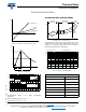
TEMPERATURE COEFFICIENT
In the leakage current region of the V/I characteristic, the
normal equation V = C x I
of the varistor becomes less
applicable.
This is due to a parallel resistance which shows a very
important temperature coefficient, created by thermal
conduction. This temperature coefficient decreases when
the current density increases. Then, the temperature
coefficient at 1 mA is higher for a large varistor than for a
small varistor.
This phenomena induces an increase in leakage current
when the varistor is used at high temperatures. The
relationship between the temperature and the current at a
given voltage can be expressed by:
I = I
0
x e
KT
where:
I
0
is the limiting current at 0 K
K is a constant including the band gap energy of the
zinc oxide and the Boltzmann’s constant.
Practically, the maximum temperature coefficient is
guaranteed on the voltage for a current of 1 mA in % per K.
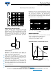
SURGE PROTECTION
Varistors provide protection against surges which may be
generated in the following ways:
ELECTROMAGNETIC ENERGY
Atmospheric, lightning
Switching of inductive loads:
• Relays
• Pumps
•Actuators
• Spot welders
• Thermostats
• Fluorescent chokes
• Discharge lamps
• Motors
• Transformers
• Air conditioning units
•Fuses
ELECTROSTATIC DISCHARGES
For example, discharges caused by synthetic carpets
(approximately 50 kV), due to the inductance of the
connecting leadwires, the reaction time of leaded VDR’s
might be too slow to clamp properly fast rising ESD pulses.
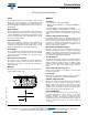
SOURCE OF TRANSIENT
The energy dissipated by switching of an inductive load is
completely transferred into the capacitance of the coil which
is generally very low.
E = ½ x L x I
2
= ½ x C x V
2
P
1
---
x K x V
rms
1+
x 2
a 1 2+
x tsin
0
1+
x dt
K x V
a1+
-----------------------------------------------------------------------------------------------------------------------------
=
P
1
---
x 2
a 1 2+
x tsin
0
1+
x dt=
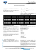
POWER RATIOS
P P P P P
1 1.0 11 14.4 21 344 31 9135 41 255 646
2 1.2 12 19.6 22 477 32 12 776 42 358 778
3 1.5 13 26.8 23 658 33 17 734 43 499 673
4 1.92 14 36.7 24 915 34 24 822 44 701 611
5 2.5 15 50.3 25 1264 35 34 482 45 977 622
6 3.29 16 69 26 1763 36 48 301 46 1 373 365
7 4.375 17 95 27 2439 37 67 149 47 1 914 510
8 5.85 18 131 28 3404 38 94 126 48 2 690 675
9 7.875 19 180 29 4715 39 130 941 49 3 752 439
10 10.64 20 249 30 6587 40 183 660 50 5 275 834