
Brochure


Varistors Introduction
TECHNICAL NOTE
Technical Note
www.vishay.com
Vishay BCcomponents
Revision: 04-Sep-13
7
Document Number: 29079
For technical questions, contact: nlr@vishay.com
THIS DOCUMENT IS SUBJECT TO CHANGE WITHOUT NOTICE. THE PRODUCTS DESCRIBED HEREIN AND THIS DOCUMENT
ARE SUBJECT TO SPECIFIC DISCLAIMERS, SET FORTH AT www.vishay.com/doc?91000
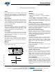
Examples
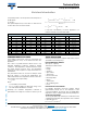
Pulse life time rating of VDRS07H060, 60 V type.
Energy capability: E = K x V
p
x I
p
x t
2
1 pulse; 8 µs to 20 µs: 1200 A = 1 x 8 J
10 pulses; 8 µs to 20 µs: 300 A = 10 x 1.45 J
1 pulse; 10 µs to 1000 µs: 33A = 1 x 8.3 J
10 pulses; 10 µs to 1000 µs: 11 A = 10 x 2.5 J
The maximum specified energy is defined for a maximum
shift (V/V) 1 mA 10 %:
I
p
= Pulse current
V
p
= Corresponding clamping voltage
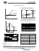
Typical surge life rating curves (number of surges allowed as
a function of pulse time and maximum current) are shown in
drawing below.
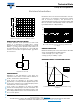
Maximum peak current for various number of pulses as a function
of pulse duration
E = K x V
peak
x I
peak
x t
2
= 1.4 x 700 x 33 x 10
-3
= 32 J
Example of calculation of energy for a VDRS07H250 type,
at the maximum peak current (33 A) for a duration
t
2
= 1000 μs (K = 1.4)
Maximum energy (10 x 1000 μs): 1 pulse
Example: VDRS07H250 (250 V)
Example of selection of the maximum peak current as a
function of pulse duration.
DISSIPATED POWER
DC DISSIPATION
The power dissipated in a varistor is equal to the product of
the voltage and current, and may be written:
W = I x V = C x I
+ 1
or K x V
+ 1
When the coefficient = 30 ( = 0.033), the power
dissipated by the varistor is proportional to the 31
st
power of
the voltage. A voltage increase of only 2.26 % will, in this
case, double the dissipated power. Consequently, it is very
important that the applied voltage does not rise above a
certain maximum value, or the permissible rating will be
exceeded.
This is even more cogent as the varistors have a negative
temperature coefficient, which means that at a higher
dissipation (and accordingly at a higher temperature) the
resistance value will decrease and the dissipated power will
increase further.
AC DISSIPATION
When a sinusoidal alternating voltage is applied to a varistor,
the dissipation cannot be calculated from the same formula
as in a DC application. The calculation requires an
integration of the V x I product.
The instantaneous dissipated power is given by:
In the above equation, the value V = V
peak
x sin t.
During a half cycle, the dissipated power is given by:
Since V
peak
= V
RMS
x 2x
This integration is not easy to solve because of the exponent
+ 1) of sin t.
K DEPENDS ON t
2
WHEN t
1
IS 8 μs TO 10 μs
t
2
(μs)
K
20 1
50 1.2
100 1.3
1000 1.4
10
-3
10
-2
10
-1
1
reduction factor
of rated pulse
peak current
10 10
2
10
3
10
4
t
p
(µs)
100
10
6
1000
1
10
10
2
100
10
-3
V
peak
(V)
429
690
1000
10
-2
10
-1
1
I (A)
33
10
10 10
2
10
3
10
4
t
p
(µs)
10
5
I
(A)
33
I
peak
P
INST
V x I V== K x V
K= x V
1+
P
RMS
1
---
0
K x V
peak
1+
x tsin
1+
x d=
P
RMS
1
---
x K x V
RMS
1+
x 2
a1+
x tsin
0
1+
x dt=