
Brochure


Varistors Introduction
TECHNICAL NOTE
Technical Note
www.vishay.com
Vishay BCcomponents
Revision: 04-Sep-13
6
Document Number: 29079
For technical questions, contact: nlr@vishay.com
THIS DOCUMENT IS SUBJECT TO CHANGE WITHOUT NOTICE. THE PRODUCTS DESCRIBED HEREIN AND THIS DOCUMENT
ARE SUBJECT TO SPECIFIC DISCLAIMERS, SET FORTH AT www.vishay.com/doc?91000
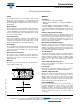
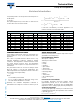
Influence on varistor when V
1
is 1000 V (R = 250 )
EQUIVALENT CIRCUIT MODEL
A simple equivalent circuit representing a metal oxide
varistor as a capacitance in parallel with a voltage
dependent resistor is shown in the Equivalent circuit model
drawing. C
p
and R
p
are the capacitance and resistance of
the intergranular layer respectively; R
g
is the ZnO grain
resistance. For low values of applied voltages, R
p
behaves
as an ohmic loss.
Equivalent circuit model
CAPACITANCE
Depending on area and thickness of the device, the
capacitance of the varistor increases with the diameter of
the disc, and decreases with its thickness.
In DC circuits, the capacitance of the varistor remains
approximately constant provided the applied voltage does
not rise to the conduction zone, and drops abruptly near the
rated maximum continuous DC voltage.
In AC circuits, the capacitance can affect the parallel
resistance in the leakage region of the V/I characteristic. The
relationship is approximately linear with the frequency and
the resulting parallel resistance can be calculated from 1/C
as for a usual capacitor.
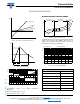
Nevertheless, due to the structural characteristic of the zinc
oxide varistors, the capacitance itself decreases slightly
with an increase in frequency. This phenomenon is
emphasized when the frequency reaches approximately 100
kHz. See the effect of HF alternating current on the varistor
type VDRS14T250; C = 480 pF drawing.
Effect of HF alternating current on varistor type VDRS14T250;
C = 480 pF
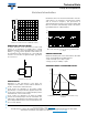
ENERGY HANDLING
Maximum allowable peak current and maximum allowable
energy are standardized using defined pulses:
• Peak current (A); 8 μs to 20 μs, 1 pulse
• Energy (J); 10 μs to 1000 μs, 1 pulse
INTERNATIONALLY ACCEPTED PULSES
Standard pulse for current and maximum allowable energy
calculation
V
R
V
O
V
1
V
(V)
1000
800
600
400
200
0
02
I (A)
46
810
R
g
I
C
p
R
p
- U
10
-2
10
-1
110
10
3
10
2
10
V
(V)
I (mA)
50 Hz 100 Hz 1 kHz 10 kHz
100 kHz
t
t
2
t
1
I
peak
(%)
100
50
t
1
8 µs
10 µs
t
2
20 µs
1000 µs