
Datasheet


VCNL36687S
www.vishay.com
Vishay Semiconductors
Rev. 1.2, 21-Sep-2018
8
Document Number: 84907
For technical questions, contact: sensorstechsupport@vishay.com
THIS DOCUMENT IS SUBJECT TO CHANGE WITHOUT NOTICE. THE PRODUCTS DESCRIBED HEREIN AND THIS DOCUMENT
ARE SUBJECT TO SPECIFIC DISCLAIMERS, SET FORTH AT www.vishay.com/doc?91000
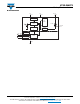
Function Description
For proximity sensor function, VCNL36687S supports different kinds of mechanical designs to achieve the best proximity
detection performance for any color of object with more flexibility. The basic PS function settings, such as period, persistence,
INT, and shut down are handled by the register: PS_CONF1. Period controls the PS response time. Integration time represents
the duration of the energy being received. The Interrupt is asserted when the PS detection levels over the high threshold level
setting (register: PS_THDH) or lower than low threshold (register: PS_THDL). If the Interrupt function is enabled, the host reads
the PS output data from VCNL36687S that saves host loading from periodically reading PS data. More than that, INT flag
(register: INT_Flag) indicates the behavior of INT triggered under different conditions. PS persistence (PS_PERS) sets up the PS
INT asserted conditions as long as the PS output value continually exceeds the threshold level. The intelligent cancellation level
can be set on register: PS_CANC to reduce the cross talk phenomenon.
VCNL36687S also supports easy use of proximity detection logic output mode that outputs just high / low levels saving loading
from the host. Normal operation mode or proximity detection logic output mode can be selected on the register: PS_MS.
A smart persistence is provided to get faster PS response time and prevent false trigger for PS. Descriptions of each slave
address operation are shown in Table 1.
Note
• All of reserved register are used for internal test. Please keep as default setting
TABLE 1 - COMMAND CODE AND REGISTER DESCRIPTION
COMMAND
CODE
DATE BYTE
LOW / HIGH
REGISTER
NAME
R / W
DEFAULT
VALUE
FUNCTION DESCRIPTION
0x03
L PS_CONF1 R / W 0x01 PS period, persistence, INT and smart persistence and function selection
H PS_CONF2 R / W 0x00 PS IT and start selection
0x04
L PS_CONF3 R / W 0x00 PS active force mode
H PS_CONF4 R / W 0x00 PS VCSEL current selection
0x05
L PS_THDL_L R / W 0x00 PS low interrupt threshold setting LSB byte
H PS_THDL_M R / W 0x00 PS low interrupt threshold setting MSB byte
0x06
L PS_THDH_L R / W 0x00 PS high interrupt threshold setting LSB byte
H PS_THDH_M R / W 0x00 PS high interrupt threshold setting MSB byte
0x07
L PS_CANC_L R / W 0x00 PS cancellation level setting
H PS_CANC_M R / W 0x00 PS cancellation level setting
0x08
L PS_CONF5 R / W 0x00 PS power on start setting
H Reserved R / W 0x00 Reserved
0xF2
L PS_Data_L R 0x00 PS LSB output data
H PS_Data_M R 0x00 PS MSB output data
0xF3
L Reserved R 0x00 Reserved
H INT_Flag R 0x00 PS interrupt flags
0xF4
L ID_L R 0x88 Device ID LSB
H ID_M R 0x05 Device ID MSB