
Datasheet


VCNL36687S
www.vishay.com
Vishay Semiconductors
Rev. 1.2, 21-Sep-2018
14
Document Number: 84907
For technical questions, contact: sensorstechsupport@vishay.com
THIS DOCUMENT IS SUBJECT TO CHANGE WITHOUT NOTICE. THE PRODUCTS DESCRIBED HEREIN AND THIS DOCUMENT
ARE SUBJECT TO SPECIFIC DISCLAIMERS, SET FORTH AT www.vishay.com/doc?91000
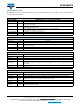
RECOMMENDED INFRARED REFLOW
Soldering conditions which are based on J-STD-020 C
Recommend Normal Solder Reflow is 235 °C to 265 °C
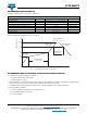
Fig. 13 - VCNL36687S Solder Reflow Profile Chart
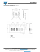
RECOMMENDED IRON TIP SOLDERING CONDITION AND WARNING HANDLING
1. Solder the device with the following conditions:
1.1. Soldering temperature: 400 °C (max.)
1.2. Soldering time: 3 s (max.)
2. If the temperature of the method portion rises in addition to the residual stress between the leads, the possibility that an
open or short circuit occurs due to the deformation or destruction of the resin increases
3. The following methods: VPS and wave soldering, have not been suggested for the component assembly
4. Cleaning method conditions:
4.1. Solvent: methyl alcohol, ethyl alcohol, isopropyl alcohol
4.2. Solvent temperature < 45 °C (max.)
4.3. Time: 3 min (min.)
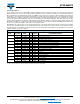
IR REFLOW PROFILE CONDITION
PARAMETER CONDITIONS TEMPERATURE TIME
Peak temperature 260 °C + 5 °C / - 5 °C (max.: 265 °C) 10 s
Preheat temperature range and timing 150 °C to 200 °C 60 s to 180 s
Timing within 5 °C to peak temperature - 10 s to 30 s
Timing maintained above temperature / time 217 °C 60 s to 150 s
Timing from 25 °C to peak temperature - 8 min (max.)
Ramp-up rate 3 °C/s (max.) -
Ramp-down rate 6 °C/s (max.) -
200
150
217
260
Temperature (°C)
Time (s)
t
2
t
1
Max. Temperature
260 °C + 5 °C / - 5 °C/10 s
Ramp-Up Rate
3 °C/s (max.)
Soldering Zone
60 s to 150 s
Ramp-Up Rate
3 °C/s (max.)
Pre-Heating Time
t
2
- t
1
= 60 s to 180 s
Ramp-Down Rate
6 °C/s (max.)