
Datasheet
V10PL45-M3
www.vishay.com
Vishay General Semiconductor
Revision: 09-Dec-13
2
Document Number: 89479
For technical questions within your region: DiodesAmericas@vishay.com
, DiodesAsia@vishay.com, DiodesEurope@vishay.com
THIS DOCUMENT IS SUBJECT TO CHANGE WITHOUT NOTICE. THE PRODUCTS DESCRIBED HEREIN AND THIS DOCUMENT
ARE SUBJECT TO SPECIFIC DISCLAIMERS, SET FORTH AT www.vishay.com/doc?91000
Notes
(1)
Pulse test: 300 μs pulse width, 1 % duty cycle
(2)
Pulse test: Pulse width 40 ms
Notes
(1)
Free air, mounted on recommended copper pad area; thermal resistance R
JA
- junction to ambient
(2)
Mounted on 30 mm x 30 mm aluminum PCB; thermal resistance R
JM
- junction to mount
RATINGS AND CHARACTERISTICS CURVES (T
A
= 25 °C unless otherwise noted)
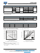
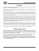
Fig. 1 - Maximum Forward Current Derating Curve
Notes
(1)
Mounted on 30 mm x 30 mm aluminum PCB; T
M
measured
at the terminal of cathode band (R
JM
= 4 °C/W)
(2)
Free air, mounted on recommended copper pad area
(R
JA
= 68 °C/W)
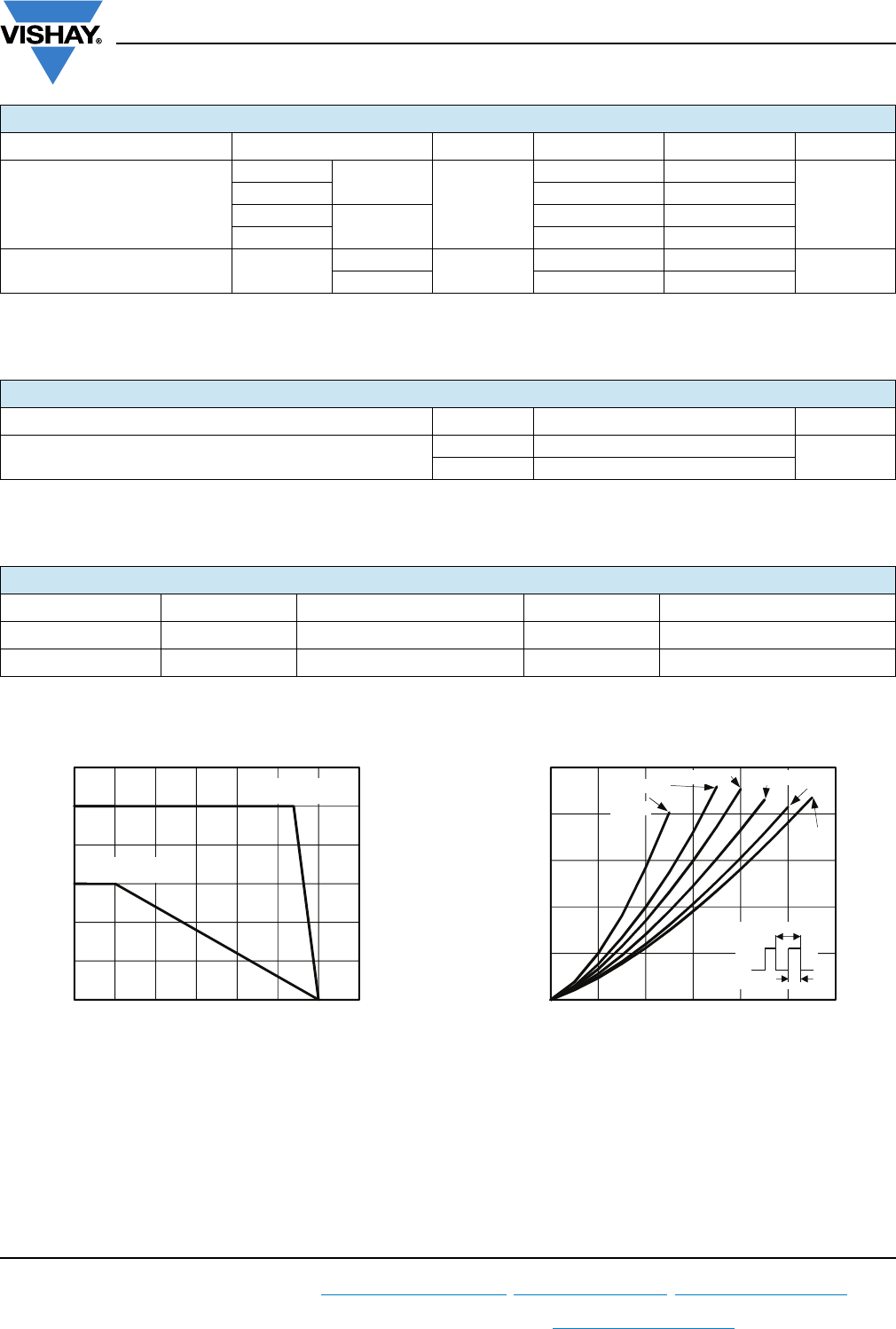
Fig. 2 - Forward Power Loss Characteristics
ELECTRICAL CHARACTERISTICS (T
A
= 25 °C unless otherwise noted)
PARAMETER TEST CONDITIONS SYMBOL TYP. MAX. UNIT
Instantaneous forward voltage
I
F
= 5.0 A
T
A
= 25 °C
V
F
(1)
0.39 -
V
I
F
= 10 A 0.44 0.52
I
F
= 5.0 A
T
A
= 125 °C
0.28 -
I
F
= 10 A 0.35 0.43
Reverse current V
R
= 45 V
T
A
= 25 °C
I
R
(2)
-5.0
mA
T
A
= 125 °C 30 75
THERMAL CHARACTERISTICS (T
A
= 25 °C unless otherwise noted)
PARAMETER SYMBOL V10PL45 UNIT
Typical thermal resistance
R
JA
(1)
68
°C/W
R
JM
(2)
4
ORDERING INFORMATION (Example)
PREFERRED P/N UNIT WEIGHT (g) PREFERRED PACKAGE CODE BASE QUANTITY DELIVERY MODE
V10PL45-M3/86A 0.10 86A 1500 7" diameter plastic tape and reel
V10PL45-M3/87A 0.10 87A 6500 13" diameter plastic tape and reel
0
2
4
6
8
10
12
0 25 50 75 100 125 150 175
Average Forward Rectied Current (A)
T
M
- Mount Temperature (°C)
T
A
= 25 °C
T
M
= 130 °C
0.0
1.0
2.0
3.0
4.0
5.0
024681012
Average Power Loss (W)
Average Forward Current (A)
D = 0.1
D = 0.2
D = 0.3
D = 0.5
D = 1.0
D = 0.8
D = t
p
/T
T
t
p