
Datasheet
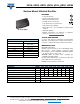

US1A, US1B, US1D, US1G, US1J, US1K, US1M
www.vishay.com
Vishay General Semiconductor
Revision: 28-Apr-14
2
Document Number: 88768
For technical questions within your region: DiodesAmericas@vishay.com
, DiodesAsia@vishay.com, DiodesEurope@vishay.com
THIS DOCUMENT IS SUBJECT TO CHANGE WITHOUT NOTICE. THE PRODUCTS DESCRIBED HEREIN AND THIS DOCUMENT
ARE SUBJECT TO SPECIFIC DISCLAIMERS, SET FORTH AT www.vishay.com/doc?91000
Note
(1)
Pulse test: 300 μs pulse width, 1 % duty cycle
Note
(1)
PCB mounted on 0.2" x 0.2" (5.0 mm x 5.0 mm) copper pad area
Note
(1)
AEC-Q101 qualified
RATINGS AND CHARACTERISTICS CURVES (T
A
= 25 °C unless otherwise noted)
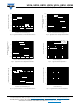
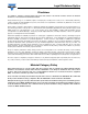
Fig. 1 - Forward Current Derating Curve Fig. 2 - Maximum Non-Repetitive Peak Forward Surge Current
ELECTRICAL CHARACTERISTICS (T
A
= 25 °C unless otherwise noted)
PARAMETER TEST CONDITIONS SYMBOL US1A US1B US1D US1G US1J US1K US1M UNIT
Maximum instantaneous forward
voltage
1.0 A V
F
(1)
1.0 1.7 V
Maximum DC reverse current
at rated DC blocking voltage
T
A
= 25 °C
I
R
10
μA
T
A
= 100 °C 50
Maximum reverse recovery time
I
F
= 0.5 A, I
R
= 1.0 A,
I
rr
= 0.25 A
t
rr
50 75 ns
Typical junction capacitance 4.0 V, 1 MHz C
J
15 10 pF
THERMAL CHARACTERISTICS (T
A
= 25 °C unless otherwise noted)
PARAMETER SYMBOL US1A US1B US1D US1G US1J US1K US1M UNIT
Maximum thermal resistance
R
JA
(1)
75
°C/W
R
JL
(1)
27
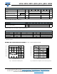
ORDERING INFORMATION (Example)
PREFERRED P/N UNIT WEIGHT (g) PREFERRED PACKAGE CODE BASE QUANTITY DELIVERY MODE
US1J-E3/61T 0.064 61T 1800 7" diameter plastic tape and reel
US1J-E3/5AT 0.064 5AT 7500 13" diameter plastic tape and reel
US1JHE3_A/H
(1)
0.064 H 1800 7" diameter plastic tape and reel
US1JHE3_A/I
(1)
0.064 I 7500 13" diameter plastic tape and reel
0
0.4
1.2
0
7525 50
100 125
150
0.8
0.2
0.6
1.0
Resistive or Inductive Load
Lead Temperature (°C)
Average Forward Rectified Current (A)
0.2" x 0.2" (5.0 mm x 5.0 mm)
Copper Pad Areas
0
15
20
25
10
5
30
Number of Cycles at 60 Hz
Peak Forward Surge Current (A)
1 10 100
T
L
= 110 °C
8.3 ms Single Half Sine-Wave