
Datasheet

Document Number: 88763 For technical questions within your region, please contact one of the following: www.vishay.com
Revision: 23-Oct-09 DiodesAmericas@vishay.com
, DiodesAsia@vishay.com, DiodesEurope@vishay.com 3
UG4A thru UG4D
Vishay General Semiconductor
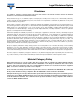
Fig. 3 - Typical Instantaneous Forward Characteristics
Fig. 4 - Typical Reverse Leakage Characteristics
Fig. 5 - Reverse Switching Charateristics
Fig. 6 - Typical Junction Capacitance
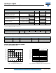
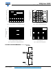
PACKAGE OUTLINE DIMENSIONS in inches (millimeters)
0.4
0.6
0.8
1.0
1.2
1.4
1.6
1.8
0.01
0.1
1
10
100
Instantaneous Forward Voltage (V)
Instantaneous Forward Current (A)
T
J
= 25 °C
T
J
= 100 °C
Pulse Width = 300 μs
1 % Duty Cycle
0
20
40
60
80
100
0.01
0.1
1
10
100
1000
Percent of Rated Peak Reverse Voltage (%)
Instantaneous Reverse Leakage
Current (μA)
T
J
= 25 °C
T
J
= 100 °C
0
25
50
75
100
125
150
175
0
10
20
30
40
50
60
Junction Temperature (°C)
Recovered Stored Change/Reverse
Recovery Time, nC/ns
I
F
= 4.0 A
V
R
= 30 V
dI/dt = 150 A/μs
dI/dt = 100 A/μs
dI/dt = 20 A/μs
dI/dt = 50 A/μs
t
rr
Q
rr
dI/dt = 150 A/μs
dI/dt = 100 A/μs
dI/dt = 20 A/μs
dI/dt = 50 A/μs
0.1
1
10
100
1
10
100
Reverse Voltage (V)
Junction Capacitance (pF)
T
J
= 25 °C
f = 1.0 MHz
V
sig
= 50 mV
p-p
DO-201AD
0.210 (5.3)
0.190 (4.8)
DIA.
0.052 (1.32)
0.048 (1.22)
DIA.
1.0 (25.4)
MIN.
1.0 (25.4)
MIN.
0.375 (9.5)
0.285 (7.2)