
Datasheet

www.vishay.com For technical questions within your region, please contact one of the following: Document Number: 88761
2 DiodesAmericas@vishay.com
, DiodesAsia@vishay.com, DiodesEurope@vishay.com Revision: 23-Oct-09
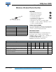
UG2A thru UG2D
Vishay General Semiconductor
Note
(1)
Pulse test: 300 μs pulse width, 1 % duty cycle
Note
(1)
Thermal resistance from junction to ambient at 0.375" (9.5 mm) lead length
RATINGS AND CHARACTERISTICS CURVES
(T
A
= 25 °C unless otherwise noted)
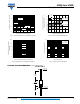
Fig. 1 - Maximum Forward Current Derating Curves Fig. 2 - Maximum Non-Repetitive Peak Forward Surge Current
ELECTRICAL CHARACTERISTICS (T
A
= 25 °C unless otherwise noted)
PARAMETER TEST CONDITIONS SYMBOL VALUE UNIT
Maximum instantaneous forward voltage I
F
= 2.0 A V
F
(1)
0.95 V
Maximum DC reverse current
at rated DC blocking voltage
T
A
= 25 °C
I
R
5.0
μA
T
A
= 100 °C 200
Maximum reverse recovery time I
F
= 0.5 A, I
R
= 1.0 A, I
rr
= 0.25 A t
rr
15 ns
Typical reverse recovery time
I
F
= 2.0 A, V
R
= 30 V,
dI/dt = 50 A/μs, I
rr
= 10 % I
RM
T
J
= 25 °C
t
rr
25
ns
T
J
= 100 °C 35
Typical stored charge
I
F
= 2.0 A, V
R
= 30 V,
dI/dt = 50 A/μs, I
rr
= 10 % I
RM
T
J
= 25 °C
Q
rr
10
nC
T
J
= 100 °C 22
Typical junction capacitance 4 V, 1 MHz C
J
15 pF
THERMAL CHARACTERISTICS (T
A
= 25 °C unless otherwise noted)
PARAMETER SYMBOL UG2A UG2B UG2C UG2D UNIT
Typical thermal resistance R
θJA
(1)
45 °C/W
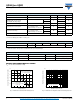
ORDERING INFORMATION (Example)
PREFERRED P/N UNIT WEIGHT (g) PREFERRED PACKAGE CODE BASE QUANTITY DELIVERY MODE
UG2D-E3/54 0.404 54 4000 13" diameter paper tape and reel
UG2D-E3/73 0.404 73 2000 Ammo pack packaging
Temperature (°C)
Average Forward Rectied Current (A)
0
25
50
75
100
125
150
175
0
0.5
1.0
1.5
2.0
2.5
3.0
T
A
, Ambient Temperature
P.C.B. Mounted
0.47" x 0.47" (12 mm x 12 mm)
Copper Pads
Resistive or Inductive Load
0.375" (9.5 mm) Lead Length
T
L
Lead Temperature
Number of Cycles at 60 Hz
Peak Forward Surge Current (A)
1
10
100
1
10
100
T
L
= 75 °C
8.3 ms Single Half Sine-Wave