
Datasheet


UF5400, UF5401, UF5402, UF5403, UF5404, UF5405, UF5406, UF5407, UF5408
www.vishay.com
Vishay General Semiconductor
Revision: 10-Feb-15
3
Document Number: 88756
For technical questions within your region: DiodesAmericas@vishay.com
, DiodesAsia@vishay.com, DiodesEurope@vishay.com
THIS DOCUMENT IS SUBJECT TO CHANGE WITHOUT NOTICE. THE PRODUCTS DESCRIBED HEREIN AND THIS DOCUMENT
ARE SUBJECT TO SPECIFIC DISCLAIMERS, SET FORTH AT www.vishay.com/doc?91000
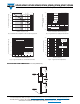
Fig. 3 - Maximum Non-Repetitive Peak Forward Surge Current
Fig. 4 - Typical Instantaneous Forward Characteristics
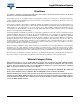
Fig. 5 - Typical Reverse Leakage Characteristics
Fig. 6 - Typical Junction Capacitance
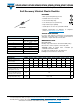
PACKAGE OUTLINE DIMENSIONS in inches (millimeters)
1
10
100
0
25
50
75
100
125
150
Number of Cycles at 60 Hz
Peak Forward Surge Current (A)
T
A
= 55 °C
8.3 ms Single Half Sine-Wave
0.4
0.6
0.8
1.0
1.2
1.4
1.6
1.8
0.01
0.1
1
10
100
Instantaneous Forward Voltage (V)
Instantaneous Forward Current (A)
T
J
= 25 °C
Pulse Width = 300 μs
1 % Duty Cycle
UF5400 thru UF5404
UF5405 thru UF5408
0
20
40
60
80
100
0.01
0.1
1
10
100
Percent of Rated Peak Reverse Voltage (%)
Instantaneous Reverse Leakage
Current (μA)
UF5400 thru UF5404
UF5405 thru UF5408
T
J
= 125 °C
T
J
= 25 °C
T
J
= 100 °C
T
J
= 125 °C
T
J
= 100 °C
0.1
1
10
100
20
40
60
80
100
120
140
160
Reverse Voltage (V)
Junction Capacitance (pF)
UF5400 thru UF5404
UF5405 thru UF5408
T
J
= 25 °C
f = 1.0 MHz
V
sig
= 50 mV
p-p
DO-201AD
0.210 (5.3)
0.190 (4.8)
DIA.
0.052 (1.32)
0.048 (1.22)
DIA.
1.0 (25.4)
MIN.
1.0 (25.4)
MIN.
0.375 (9.5)
0.285 (7.2)