
Datasheet

UF4001 thru UF4007
Vishay General Semiconductor
www.vishay.com For technical questions within your region, please contact one of the following:
PDD-Americas@vishay.com
, PDD-Asia@vishay.com, PDD-Europe@vishay.com
Document Number: 88755
Revision: 20-Aug-07
2
Note:
(1) Pulse test: 300 µs pulse width, 1 % duty cycle
Note:
(1) Thermal resistance from junction to ambient at 0.375" (9.5 mm) lead length
RATINGS AND CHARACTERISTICS CURVES
(T
A
= 25 °C unless otherwise noted)
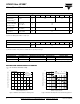
ELECTRICAL CHARACTERISTICS (T
A
= 25 °C unless otherwise noted)
PARAMETER TEST CONDITIONS SYMBOL UF4001 UF4002 UF4003 UF4004 UF4005 UF4006 UF4007 UNIT
Maximum
instantaneous
forward voltage
(1)
1.0 A V
F
1.0 1.7 V
Maximum DC reverse
current at rated DC
blocking voltage
T
A
= 25 °C
T
A
= 100 °C
I
R
10
50
µA
Maximum reverse
recovery time
I
F
= 0.5 A, I
R
= 1.0 A,
I
rr
= 0.25 A
t
rr
50 75 ns
Typical junction
capacitance
4.0 V, 1 MHz C
J
17 pF
THERMAL CHARACTERISTICS (T
A
= 25 °C unless otherwise noted)
PARAMETER SYMBOL UF4001 UF4002 UF4003 UF4004 UF4005 UF4006 UF4007 UNIT
Typical thermal resistance
(1)
R
θJA
R
θJL
60
15
°C/W
ORDERING INFORMATION (Example)
PREFERRED P/N UNIT WEIGHT (g) PREFERRED PACKAGE CODE BASE QUANTITY DELIVERY MODE
UF4007-E3/54 0.33 54 5500 13" diameter paper tape and reel
UF4007-E3/73 0.34 73 3000 Ammo pack packaging
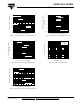
Figure 1. Maximum Forward Current Derating Curve
1.0
20
40
60
80
100
120
140
160
0
0.5
Resistive or
Inductive Load
0.375" (9.5 mm)
Lead Length
Ambient Temperature (°C)
Average Forward Rectified Current (A)
Figure 2. Maximum Non-Repetitive Peak Forward Surge Current
1
10
100
0
5
10
15
20
25
30
T
A
= 55 °C
8.3 ms Single Half Sine-Wave
Number of Cycles at 60 Hz
Peak Forward Surge Current (A)