
Datasheet
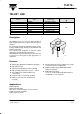

TLW.76..
Vishay Semiconductors
5 (14)Rev. A8, 07-Aug-01
www.vishay.comDocument Number 83138
White (TLWW76.. )
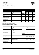
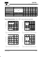
Parameter Test Conditions Type Symbol Min Typ Max Unit
Total flux
V
400 650 1250 mlm
Luminous intensity/Total flux
I
F
= 50 mA, R
t
h
J
A
=200 K/W
I
V
/
V
0.8
mcd/
mlm
Color temperature
F
,
thJA
T
K
5500 K
Angle of half intensity ϕ ±30 deg
Total included angle 90 % of Total Flux Captured ϕ 75 deg
Forward voltage I
F
= 50 mA, R
thJA
=200 K/W V
F
4.3 5.1 V
Reverse voltage I
R
= 10 A V
R
5 10 V
Junction capacitance V
R
= 0, f = 1 MHz C
j
50 pF
Typical Characteristics (T
amb
= 25 C, unless otherwise specified)
0
25
50
75
100
125
150
175
200
0 20406080100120
T
amb
– Ambient Temperature ( °C )15982
P – Power Dissipation ( mW )
V
R
thJA
=200K/W
Red, Softorange,
Yellow
Figure 1 Power Dissipation vs. Ambient Temperature
0
20
40
60
80
100
0 20406080100120
T
amb
– Ambient Temperature ( °C )15983
I – Forward Current ( mA )
F
R
thJA
=200K/W
Red, Softorange,
Yellow
Figure 2 Forward Current vs. Ambient Temperature
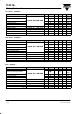
0
25
50
75
100
125
150
175
200
225
250
0 20406080100120
T
amb
– Ambient Temperature ( °C )16066
P – Power Dissipation ( mW )
V
R
thJA
=200K/W
Blue
Blue Green
True Green
White
Figure 3 Power Dissipation vs. Ambient Temperature
0
10
20
30
40
50
60
0 20406080100120
T
amb
– Ambient Temperature ( °C )16067
I – Forward Current ( mA )
F
R
thJA
=200K/W
Blue
Blue Green
True Green
White
Figure 4 Forward Current vs. Ambient Temperature