
Datasheet


VISHAY
TLUG / O / Y240.
Document Number 83053
Rev. 1.8, 31-Aug-04
Vishay Semiconductors
www.vishay.com
5
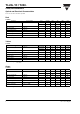
Figure 13. Rel. Lumin. Intensity vs. Forw. Current/Duty Cycle
Figure 14. Relative Luminous Intensity vs. Forward Current
Figure 15. Relative Intensity vs. Wavelength
Yellow
10 20 50 100 200
0
0.4
0.8
1.2
1.6
2.4
95 10260
500
0.5 0.2 0.1 0.05 0.021
I
F
(mA)
t
p
/T
I - Relative Luminous Intensity
v rel
2.0
Yellow
I
F
- Forward Current ( mA )
100
0.1
1
10
95 10033
I - Relative Luminous Intensity
v rel
101
0.01
550 570 590 610 630
0
0.2
0.4
0.6
0.8
1.2
650
95 10039
λ -- Wavelength ( nm )
1.0
Yellow
I - Relative Luminous Intensity
Vrel
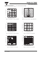
Figure 16. Forward Current vs. Forward Voltage
Figure 17. Rel. Luminous Intensity vs. Ambient Temperature
Figure 18. Specific Luminous Intensity vs. Forward Current
0.1
1
10
100
1000
1086420
95 10034
V
F
- Forward Voltage(V)
I - Forward Current ( mA )
F
Green
t
p
/T = 0.001
t
p
=10µs
0
0.4
0.8
1.2
1.6
95 10035
I - Relative Luminous Intensity
v rel
Green
I
F
=10mA
T
amb
- Ambient Temperature ( ° C)
20 40 60 800 100
10 20 50 100 200
0
0.4
0.8
1.2
1.6
2.4
95 10263
500
v rel
2.0
Green
I - Specific Luminous Intensity
I
F
(mA)
0.5 0.2 0.1 0.05 0.021
t
p
/T