
Datasheet

VISHAY
TLRG / H / O / Y4420
Document Number 83045
Rev. 1.4, 31-Aug-04
Vishay Semiconductors
www.vishay.com
3
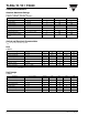
Yellow
TLRY4420
1)
in one Packing Unit I
Vmin
/I
Vmax
≤ 0.5
Green
TLRG4420
1)
in one Packing Unit I
Vmin
/I
Vmax
≤ 0.5
Typical Characteristics (T
amb
= 25 °C unless otherwise specified)
Parameter Test condition Symbol Min Ty p. Max Unit
Luminous intensity
1)
V
S
= 12 V I
V
1.6 4 mcd
Dominant wavelength V
S
= 12 V λ
d
581 594 nm
Peak wavelength V
S
= 12 V λ
p
585 nm
Angle of half intensity V
S
= 12 V ϕ ± 30 deg
Forward current V
S
= 12 V I
F
10 12 mA
Breakdown voltage I
R
= 10 µAV
BR
670 V
Junction capacitance V
R
= 0, f = 1 MHz C
j
50 pF
Parameter Test condition Symbol Min Ty p. Max Unit
Luminous intensity
1)
V
S
= 12 V I
V
1.6 4 mcd
Dominant wavelength V
S
= 12 V λ
d
562 575 nm
Peak wavelength V
S
= 12 V λ
p
565 nm
Angle of half intensity V
S
= 12 V ϕ ± 30 deg
Forward current V
S
= 12 V I
F
10 12 mA
Breakdown voltage I
R
= 10 µAV
BR
670 V
Junction capacitance V
R
= 0, f = 1 MHz C
j
50 pF
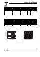
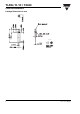
Figure 1. Forward Current vs. Forward Voltage
0
2
4
6
8
10
12
14
16
18
20
0 2 4 6 8 10 12 14 16 18 20
V
F
- Forward Voltage(V)
95 11434
F
I - Forward Current ( mA )
Red
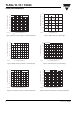
Figure 2. Relative Forward Current vs. Ambient Temperature
0.5
0.6
0.7
0.8
0.9
1.0
1.1
1.2
1.3
1.4
1.5
T
amb
- Ambient Temperature (° C)
95 11435
V
S
=12V
I - Relative Forward Current
Frel
-30 -20 -10 10 20 30 40 50 60 70 80 90 1000
Red