
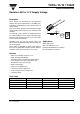
Datasheet

www.vishay.com
2
Document Number 83045
Rev. 1.4, 31-Aug-04
VISHAY
TLRG / H / O / Y4420
Vishay Semiconductors
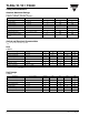
Absolute Maximum Ratings
T
amb
= 25 °C, unless otherwise specified
TLRH4420 , TLRO4420 , TLRY4420 , TLRG4420
Optical and Electrical Characteristics
T
amb
= 25 °C, unless otherwise specified
Red
TLRH4420
1)
in one Packing Unit I
Vmin
/I
Vmax
≤ 0.5
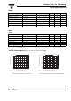
Soft Orange
TLRO4420
1)
in one Packing Unit I
Vmin
/I
Vmax
≤ 0.5
Parameter Test condition Symbol Value Unit
Reverse voltage V
R
6V
Forward voltage T
amb
≤ 65 °C V
F
16 V
Power dissipation T
amb
≤ 65 °C P
V
240 mW
Junction temperature T
j
100 °C
Operating temperature range T
amb
- 40 to + 100 °C
Storage temperature range T
stg
- 55 to + 100 °C
Soldering temperature t ≤ 5 s, 2 mm from body T
sd
260 °C
Thermal resistance junction/
ambient
R
thJA
150 K/W
Parameter Test condition Symbol Min Ty p. Max Unit
Luminous intensity
1)
V
S
= 12 V I
V
1.6 4 mcd
Dominant wavelength V
S
= 12 V λ
d
612 625 nm
Peak wavelength V
S
= 12 V λ
p
635 nm
Angle of half intensity V
S
= 12 V ϕ ± 30 deg
Forward current V
S
= 12 V I
F
10 12 mA
Breakdown voltage I
R
= 10 µAV
BR
670 V
Junction capacitance V
R
= 0, f = 1 MHz C
j
50 pF
Parameter Test condition Symbol Min Ty p. Max Unit
Luminous intensity
1)
V
S
= 12 V I
V
410 mcd
Dominant wavelength V
S
= 12 V λ
d
598 611 nm
Peak wavelength V
S
= 12 V λ
p
605 nm
Angle of half intensity V
S
= 12 V ϕ ± 30 deg
Forward current V
S
= 12 V I
F
10 12 mA
Breakdown voltage I
R
= 10 µAV
BR
670 V
Junction capacitance V
R
= 0, f = 1 MHz C
j
50 pF