
Datasheet

TFPT
www.vishay.com
Vishay
Revision: 30-Aug-16
2
Document Number: 33017
For technical questions, contact: nlr@vishay.com
THIS DOCUMENT IS SUBJECT TO CHANGE WITHOUT NOTICE. THE PRODUCTS DESCRIBED HEREIN AND THIS DOCUMENT
ARE SUBJECT TO SPECIFIC DISCLAIMERS, SET FORTH AT www.vishay.com/doc?91000
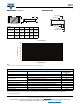
DIMENSIONS in millimeters CONSTRUCTION
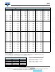
Note
• Zero power is considered as measuring power max. 1 % of rated power P
70
.
Notes
(1)
Environmental performance specifications use test procedures as outlined in MIL-R23648D, MIL-STD 202 and AEC-Q200.
(2)
TFPTs are ESD sensitive.
PART
NUMBER
ABCDE
TFPT 0603
1.55
± 0.10
0.80
± 0.10
0.45
± 0.10
0.30
± 0.20
0.30
± 0.20
TFPT 0805
2.00
± 0.15
1.25
± 0.15
0.45
± 0.10
0.40
± 0.20
0.40
± 0.20
TFPT 1206
3.05
± 0.15
1.50
± 0.15
0.55
± 0.10
0.50
± 0.25
0.50
± 0.25
A
B
D
C
E
Thermistor
Alumina substrate
Inner electrode
Nickel barrier
Solderable coating
Overcoating
TESTS AND REQUIREMENTS
TEST CONDITIONS
(1)
REQUIREMENTS
MAX |R
25
/R
25
|
High temperature exposure (storage) AEC-Q200, 1000 h at 150 °C 0.25 %
Temperature cycling AEC-Q200, 1000 cycles -55 °C / +125 °C 0.25 %
Biased humidity
1000 h, 1 mA biased at 85 °C / 85 % RH 0.25 %
1000 h, 1 mA biased at 40 °C / 95 % RH 0.25 %
Operational life 1000 h, P
70
max biased at 85 °C 0.25 %
Mechanical shock and vibration MIL-STD 202, method 213 - 204 0.50 %
Resistance to soldering heat MIL-STD 202, method 210, solderbath dipping 10 s at 260°C 0.25 %
ESD
(2)
AEC-Q200-002, HBM (CD) 0.5 kV (0603), 1.0 kV (0805), 1.0 kV (1206) 0.25 %
Board flex AEC-Q200-005, 2 mm during 60 s 0.25 %
Terminal strength AEC-Q200-006, shear test 17.7 N during 60 s 0.25 %
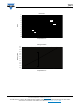
- 75 - 50 - 25 0 25 50 75 100 125 150 175
0
10
20
30
40
50
60
70
80
100
90
110
Temperature in °C
Power in % of P
70
Power Derating