
Datasheet


TCMT110. Series
www.vishay.com
Vishay Semiconductors
Rev. 3.1, 25-Jun-2018
6
Document Number: 83510
For technical questions, contact: optocoupleranswers@vishay.com
THIS DOCUMENT IS SUBJECT TO CHANGE WITHOUT NOTICE. THE PRODUCTS DESCRIBED HEREIN AND THIS DOCUMENT
ARE SUBJECT TO SPECIFIC DISCLAIMERS, SET FORTH AT www.vishay.com/doc?91000
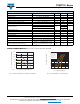
Fig. 12 - Normalized CTR (non-saturated) vs. Forward Current
Fig. 13 - Normalized CTR (saturated) vs. Forward Current
Fig. 14 - F
CTR
vs. Phase Angle
Fig. 15 - F
CTR
vs. Collector Current
Fig. 16 - Switching Time vs. Load Resistance
0
0.2
0.4
0.6
0.8
1.0
1.2
1.4
0.1 1 10 100
N
CTR
- Normalized CTR (NS)
I
F
- Forward Current (mA)
T
amb
= 0 °C
T
amb
= 100 °C
T
amb
= 75 °C
T
amb
= -55 °C
T
amb
= 25 °C
Normalized to:
I
F
= 5 mA, V
CE
= 5 V,
T
amb
= 25 °C
0
0.2
0.4
0.6
0.8
1.0
1.2
0.1 1 10 100
N
CTR
- Normalized CTR (sat)
I
F
- Forward Current (mA)
V
CE
= 0.4 V
Normalized to:
I
F
= 5 mA,
V
CE
= 5 V,
T
amb
= 25 °C
T
amb
= 0 °C
T= 75 °C
T
amb
= -55 °C-
T
amb
= 25 °C
T
amb
= 100 °C
amb
-160
-140
-120
-100
-80
-60
-40
-20
0
1 10 100 1000
Phase Angle (deg)
f - Frequency (kHz)
V
CE
= 5 V
R
L
= 100 Ω
R
L
= 1000 Ω
1
10
100
1000
0.1 1 10 100
F
CTR
(kHz)
I
C
(mA)
V
CC
= 5 V
0.1
1
10
100
1000
0 5 10 15 20
t
on
, t
off
Switching Time (μs)
R
L
- Load Resistance (kΩ)
t
off
(μs)
t
on
(μs)
V
CE
= 5 V, I
C
= 2 mA