
Datasheet


TCLT10.. Series
Document Number 83515
Rev. 2.0, 27-Sep-05
Vishay Semiconductors
www.vishay.com
7
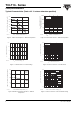
Figure 12. Collector Emitter Saturation Voltage vs. Collector
Current
Figure 13. Current Transfer Ratio vs. Forward Current
Figure 14. Turn on / off Time vs. Collector Current
110
0
0.2
0.4
0.6
0.8
1.0
V – Collector Emitter Saturation Voltage (V)
CEsat
I
C
– Collector Current ( mA )
100
CTR=50%
20%
10%
95 11028
0.1 1 10
1
10
100
1000
CTR – Current Transfer Ratio ( % )
I
F
– Forward Current ( mA )
100
95 11029
V
CE
=5V
02 4 6
0
2
4
6
8
10
I
C
– Collector Current ( mA )
10
95 11030
t / t –Turn on / T urnoff Time ( s )
off
µ
on
Non Saturated
Operation
V
S
=5V
R
L
=100 Ω
t
off
t
on
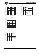
Figure 15. Turn on / off Time vs. Forward Current
0 5 10 15
0
10
20
30
40
50
I
F
– Forward Current ( mA )
20
95 11031
t / t –Turn on / T urnoff Time ( s )
off
µ
on
Saturated Operation
V
S
=5V
R
L
=1k Ω
t
off
t
on