
Datasheet


www.vishay.com
6
Document Number 83515
Rev. 2.0, 27-Sep-05
TCLT10.. Series
Vishay Semiconductors
Typical Characteristics (Tamb = 25 °C unless otherwise specified)
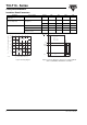
Figure 6. Total Power Dissipation vs. Ambient Temperature
Figure 7. Forward Current vs. Forward Voltage
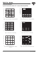
Figure 8. Relative Current Transfer Ratio vs. Ambient
Temperature
0
50
100
150
200
250
300
0 40 80 120
P –Total Power Dissipation ( mW )
T
amb
– Ambient Temperature( °C )
96 11700
tot
Coupled device
Phototransistor
IR-diode
0.1
1
10
100
1000
0 0.2 0.4 0.6 0.8 1.0 1.2 1.4 1.6 1.8 2.0
V
F
- Forward Voltage ( V )96 11862
F
I-Forward Current(mA )
–25 0 25 50
0
0.5
1.0
1.5
2.0
CTR – Relative Current Transfer Ratio
rel
T
amb
– Ambient Temperature ( °C )
95 11025
75
V
CE
=5V
I
F
=5mA
Figure 9. Collector Dark Current vs. Ambient Temperature
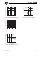
Figure 10. Collector Current vs. Forward Current
Figure 11. Collector Current vs. Collector Emitter Voltage
0255075
1
10
100
1000
10000
I - Collector Dark Current,
CEO
T
amb
- Ambient Temperature ( ° C)
100
95 11026
with open Base ( nA )
V
CE
=20V
I
F
=0
0.1 1 10
0.01
0.1
1
100
I – Collector Current ( mA)
C
I
F
– Forward Current ( mA )
100
95 11027
10
V
CE
=5V
0.1 1 10
0.1
1
10
100
V
CE
– Collector Emitter Voltage(V)
100
95 10985
I – Collector Current ( mA)
C
I
F
=50mA
5mA
2mA
1mA
20mA
10mA