
Datasheet

SS10PH9, SS10PH10
www.vishay.com
Vishay General Semiconductor
Revision: 06-Nov-13
3
Document Number: 89000
For technical questions within your region: DiodesAmericas@vishay.com
, DiodesAsia@vishay.com, DiodesEurope@vishay.com
THIS DOCUMENT IS SUBJECT TO CHANGE WITHOUT NOTICE. THE PRODUCTS DESCRIBED HEREIN AND THIS DOCUMENT
ARE SUBJECT TO SPECIFIC DISCLAIMERS, SET FORTH AT www.vishay.com/doc?91000
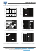
RATINGS AND CHARACTERISTICS CURVES (T
A
= 25 °C unless otherwise specified)
Fig. 1 - Maximum Forward Current Derating Curve
Fig. 2 - Forward Power Loss Characteristics Per Diode
Fig. 3 - Typical Instantaneous Forward Characteristics Per Diode
Fig. 4 - Typical Reverse Characteristics Per Diode
Fig. 5 - Typical Junction Capacitance Per Diode
Fig. 6 - Typical Transient Thermal Impedance Per Diode
10
12
8
6
4
2
0
25 50 75
100 125 150 175
Average Forward Rectified Current (A)
Lead Temperature (°C)
Resistive or Inductive Load
T
L
measured
at the Cathode Band Terminal
0
1.5
3.0
4.5
6.0
7.5
9.0
0 1 2 3 4 5 6 7 8 9 10 11
Average Forward Current (A)
Average Power Loss (W)
D = 0.1
D = 0.2
D = 0.3
D = 0.5
D = 0.8
D = 1.0
D = t
p
/T t
p
T
0.01
0.1
1
10
100
0.1 0.2 0.3 0.4 0.5 0.6 0.7 0.8 0.9 1.0
Instantaneous Forward Voltage (V)
Instantaneous Forward Current (A)
T
A
= 175 °C
T
A
= 150 °C
T
A
= 125 °C
T
A
= 25 °C
0.00001
0.0001
0.001
0.01
0.1
1
10
10 20 30 40 50 60 70 80 90 100
T
A
= 175 °C
T
A
= 150 °C
T
A
= 125 °C
T
A
= 25 °C
Percent of Rated Peak Reverse Voltage (%)
Instantaneous Reverse Current (mA)
10
100
1000
0.1 1 10 100
Reverse Voltage (V)
Junction Capacitance (pF)
T
J
= 25 °C
f = 1.0 MHz
V
sig
= 50 mV
p-p
Junction to Ambient
0.01 0.1 1 10 100
1
10
100
t - Pulse Duration (s)
Transient Thermal Impedance (°C/W)