
Datasheet

SML4728 to SML4764A
www.vishay.com
Vishay Semiconductors
Rev. 1.9, 26-May-14
3
Document Number: 85782
For technical questions within your region: DiodesAmericas@vishay.com
, DiodesAsia@vishay.com, DiodesEurope@vishay.com
THIS DOCUMENT IS SUBJECT TO CHANGE WITHOUT NOTICE. THE PRODUCTS DESCRIBED HEREIN AND THIS DOCUMENT
ARE SUBJECT TO SPECIFIC DISCLAIMERS, SET FORTH AT www.vishay.com/doc?91000
BASIC CHARACTERISTICS (T
amb
= 25 °C, unless otherwise specified)
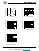
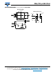
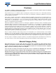
Fig. 1 - Maximum Continuous Power Dissipation
Fig. 2 - Typical Zener Impedance
Fig. 3 - Typical Temperature Coefficients
Fig. 4 - Typical Instantaneous Forward Characteristics
for SML4763
Fig. 5 - Typical Reverse Characteristics
25
50
75
100
125
150
175
0
0.25
0.5
0.75
1.0
Terminals Temperature ( °C)
P
M(AV)
,Average Power Dissipation (W)
60 Hz
Resistiveor
Inductive Load
PCB Mounted on
0.31 x 0.31 x 0.08" (8x8x2mm)
copper areas pads
17923
0.5
10
100
500
1
10
100
1,000
I
ZT
, Zener Test Current (mA)
Z
Z
, Dynamic Zener Impedance (Ω)
T
J
=25°C
V
Z
= 91V
V
Z
= 56V
V
Z
= 30V
V
Z
= 6.2V
17925
0
10
20
30
40
50
60
70
80
90
100
0
10
30
50
70
90
110
V
Z
, Zener Voltage (V)
Θ V
Z
, Temperature Coefficient (mV/ °C)
Tested at rated I
ZT
17927
0.4
0.6
0.8
1.0
1.2
1.4
1.6
0.01
0.1
1
10
Instantaneous Forward Voltage (V)
Instantaneous Forward Current (A)
Pulse width = 300µs
1% Duty Cycle
T
J
=25°C
17924
0
20
40
60
80
100
0.01
0.1
1
10
Percent of Rated Zener Voltage (%)
InstantaneousReverse Current ( µA)
T
J
=25°C
T
J
= 100°C
17926