
Datasheet

SMCJ5.0A thru SMCJ188CA
www.vishay.com
Vishay General Semiconductor
Revision: 24-Jan-2019
4
Document Number: 88394
For technical questions within your region: DiodesAmericas@vishay.com
, DiodesAsia@vishay.com, DiodesEurope@vishay.com
THIS DOCUMENT IS SUBJECT TO CHANGE WITHOUT NOTICE. THE PRODUCTS DESCRIBED HEREIN AND THIS DOCUMENT
ARE SUBJECT TO SPECIFIC DISCLAIMERS, SET FORTH AT www.vishay.com/doc?91000
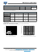
Fig. 3 - Pulse Waveform
Fig. 4 - Typical Junction Capacitance Uni-Directional
Fig. 5 - Typical Transient Thermal Impedance
Fig. 6 - Maximum Non-Repetitive Peak Forward Surge Current
Uni-Directional Use On
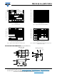
PACKAGE OUTLINE DIMENSIONS in inches (millimeters)
0
50
100
150
t
r
= 10 µs
Peak value
I
PPM
Half value -
I
PPM
I
PP
2
t
d
10/1000 µs waveform
as defined by R.E.A.
0
1.0
2.0
3.0 4.0
t - Time (ms)
I
PP
M
- Peak Pulse Current, % I
R
S
M
T
J
= 25 °C
Pulse width (t
d
)
is defined as the point
where the peak current
decays to 50 % of I
PPM
10
100
1000
10 000
20 000
101 100 400
Uni-directional
Bi-directional
T
J
= 25 °C
f = 1.0 MHz
V
sig
= 50 mVp-p
Measured at
zero bias
V
R
, measured at
Stand-off voltage V
WM
C
J
- Junction Capacitance (pF)
V
WM
- Reverse Stand-Off Voltage (V)
0.1
1.0
10
100
0.001 0.01 0.1 10 1 100 1000
t
p
- Pulse Duration (s)
Transient Thermal Impedance (°C/W)
1
10
100
10
100
200
T
J
= T
J
max.
8.3 ms single half sine-wave
Number of Cycles at 60 Hz
Peak Forward Surge Current (A)
0.260 (6.60)
0.280 (7.11)
0.006 (0.152)
0.012 (0.305)
0.030 (0.76)
0.060 (1.52)
0.008 (0.2)
0.305 (7.75)
0.320 (8.13)
0.220 (5.59)
0.246 (6.22)
0.079 (2.06)
0.103 (2.62)
0.114 (2.90)
0.126 (3.20)
Cathode Band
SMC (DO-214AB)
0.320 REF.
0.060 (1.52)
MIN.
Mounting Pad Layout
0 (0)
0.126 (3.20)
MIN.
0.185 (4.69)
MAX.