
Datasheet

New Product
SM8S10 thru SM8S43A
www.vishay.com
Vishay General Semiconductor
Revision: 14-Sep-11
4
Document Number: 88387
For technical questions within your region: DiodesAmericas@vishay.com
, DiodesAsia@vishay.com, DiodesEurope@vishay.com
THIS DOCUMENT IS SUBJECT TO CHANGE WITHOUT NOTICE. THE PRODUCTS DESCRIBED HEREIN AND THIS DOCUMENT
ARE SUBJECT TO SPECIFIC DISCLAIMERS, SET FORTH AT www.vishay.com/doc?91000
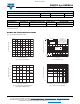
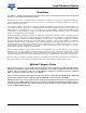
Fig. 5 - Typical Transient Thermal Impedance Fig. 6 - Typical Junction Capacitance
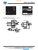
PACKAGE OUTLINE DIMENSIONS in inches (millimeters)
t - Pulse Width (s)
100
10
1
0.1
0.01
0.01 0.1 1 10 100
R
θJC
R
θJA
Transient Thermal Impedance (°C/W)
V
WM
- Reverse Stand-Off Voltage (V)
100 000
10 000
1000
10
C
J
- Junction Capacitance (pF)
403530252015 45
Measured at Stand-Off
Voltage V
WM
Measured at Zero Bias
T
J
= 25 °C
f = 1.0 MHz
V
sig
= 50 mV
p-p
DO-218AB
Mounting Pad Layout
0.413 (10.5)
0.374 (9.5)
0.091 (2.3)
0.067 (1.7)
0.116 (3.0)
0.093 (2.4)
0.150 (3.8)
0.126 (3.2)
0.366 (9.3)
0.343 (8.7)
0.606 (15.4)
0.583 (14.8)
0.116 (3.0)
0.093 (2.4)
0.628 (16.0)
0.592 (15.0)
0.539 (13.7)
0.524 (13.3)
0.366 (9.3)
0.343 (8.7)
0.406 (10.3)
0.382 (9.7)
0.342 (8.7)
0.327 (8.3)
0.413 (10.5)
0.374 (9.5)
0.028 (0.7)
0.020 (0.5)
0.138 (3.5)
0.098 (2.5)
Lead 1
0.098 (2.5)
0.059 (1.5)
Lead 2/Metal Heatsink
0.197 (5.0)
0.185 (4.7)
0.016 (0.4) MIN.