
Datasheet


www.vishay.com
4
Document Number 83662
Rev. 1.4, 26-Oct-04
VISHAY
SFH600
Vishay Semiconductors
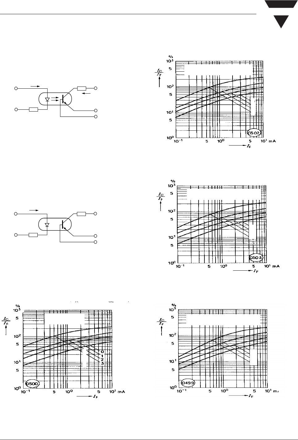
Typical Characteristics (Tamb = 25 °C unless otherwise specified)
Figure 1. Linear Operation ( without Saturation)
Figure 2. Switching Operation (with Saturation)
Figure 3. Current Transfer Ratio vs. Diode Current
isfh600_01
R
L
=75Ω
V
CC
=5V
I
C
47 Ω
I
F
I
F
1KΩ
V
CC
=5V
47 Ω
isfh600_02
0
1
2
3
isfh600_03
(T
A
= –25°C, V
CE
= 5.0 V)
I
C
/I
F
=f(I
F
)
Figure 4. Current Transfer Ratio vs. Diode Current
Figure 5. Current Transfer Ratio vs. Diode Current
Figure 6. Current Transfer Ratio vs. Diode Current
0
1
2
3
isfh600_04
(T
A
=0°C,V
CE
= 5.0 V)
I
C
/I
F
=f(I
F
)
0
1
2
3
isfh600_05
(V
CE
= 5.0 V) I
C
/I
F
=f(I
F
)
0
1
2
3
isfh600_06
(T
A
= 50°C, I
C
/I
F
=f(I
F
)
A