
User guide

Document Number: 93167 For technical questions, contact: ind-modules@vishay.com
www.vishay.com
Revision: 14-May-08 3
SD1053C..L Series
Fast Recovery Diodes
(Hockey PUK Version),
920/1050 A
Vishay High Power Products
Note
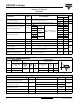
• The table above shows the increment of thermal resistance R
thJ-hs
when devices operate at different conduction angles than DC
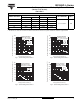
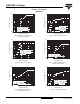
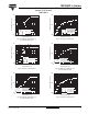
Fig. 1 - Current Ratings Characteristics
Fig. 2 - Current Ratings Characteristics
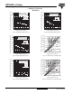
Fig. 3 - Current Ratings Characteristics
Fig. 4 - Current Ratings Characteristics
ΔR
thJ-hs
CONDUCTION
CONDUCTION ANGLE
SINUSOIDAL CONDUCTION RECTANGULAR CONDUCTION
TEST CONDITIONS UNITS
SINGLE SIDE DOUBLE SIDE SINGLE SIDE DOUBLE SIDE
180° 0.009 0.008 0.006 0.006
T
J
= T
J
maximum K/W
120° 0.011 0.011 0.011 0.011
90° 0.014 0.014 0.015 0.015
60° 0.020 0.021 0.021 0.022
30° 0.036 0.036 0.036 0.036
40
60
80
100
120
140
160
0 100 200 300 400 500 600 700
30°
60°
90°
120°
180°
Average Forward Current (A)
Maximum Allowable Heatsink Temperature (°C)
Conduction Angle
SD1053C ..S20L Series
(Single Side Cooled)
R (DC) = 0.073 K/ W
thJ-hs
20
40
60
80
100
120
140
160
0 200 400 600 800 1000 1200
30°
60°
90°
180°
DC
120°
Average Forward Current (A)
Maximum Allowable Heatsink Temperature (°C)
Conduction Period
SD 1 0 5 3 C . . S20L Serie s
(Single Side Cooled)
R (DC) = 0.073 K/ W
thJ-hs
20
40
60
80
100
120
140
160
0 100 200 300 400 500 600
30°
60°
90°
120°
180°
Average Forward Current (A)
Maximum Allowable Heatsink Temperature (°C)
Conduction Angle
SD1053C..S30L Series
(Single Side Cooled)
R (DC) = 0.073 K/ W
thJ-hs
0
20
40
60
80
100
120
140
160
0 200 400 600 800 1000
30°
60°
90°
180°
DC
120°
Average Forward Current (A)
Maximum Allowable Heatsink Temperature (°C)
Conduction Period
SD 1 0 5 3 C . . S3 0 L Se r i e s
(Single Side Cooled)
R (DC) = 0.073 K/ W
thJ-hs