
Datasheet

SB3H90, SB3H100
www.vishay.com
Vishay General Semiconductor
Revision: 13-Aug-13
2
Document Number: 88720
For technical questions within your region: DiodesAmericas@vishay.com
, DiodesAsia@vishay.com, DiodesEurope@vishay.com
THIS DOCUMENT IS SUBJECT TO CHANGE WITHOUT NOTICE. THE PRODUCTS DESCRIBED HEREIN AND THIS DOCUMENT
ARE SUBJECT TO SPECIFIC DISCLAIMERS, SET FORTH AT www.vishay.com/doc?91000
Notes
(1)
Pulse test: 300 μs pulse width, 1 % duty cycle
(2)
Pulse test: Pulse width 40 ms
Note
(1)
PCB mounted with 0.2" x 0.2" (5.0 mm x 5.0 mm) copper pad areas
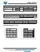
RATINGS AND CHARACTERISTICS CURVES
(T
A
= 25 °C unless otherwise noted)
Fig. 1 - Forward Current Derating Curve Fig. 2 - Maximum Non-Repetitive Peak Forward Surge Current
ELECTRICAL CHARACTERISTICS (T
A
= 25 °C unless otherwise noted)
PARAMETER TEST CONDITIONS SYMBOL SB3H90 SB3H100 UNIT
Maximum instantaneous
forward voltage
I
F
= 3.0 A
T
J
= 25 °C
V
F
(1)
0.80
V
T
J
= 125 °C 0.65
Maximum reverse current
at rated V
R
T
J
= 25 °C
I
R
(2)
20 μA
T
J
= 125 °C 4.0 mA
THERMAL CHARACTERISTICS (T
A
= 25 °C unless otherwise noted)
PARAMETER SYMBOL SB3H90 SB3H100 UNIT
Maximum thermal resistance
R
JA
(1)
50
°C/W
R
JL
(1)
20
ORDERING INFORMATION (Example)
PREFERRED P/N UNIT WEIGHT (g) PREFERRED PACKAGE CODE BASE QUANTITY DELIVERY MODE
SB3H100-E3/54 1.09 54 1400 13" diameter paper tape and reel
SB3H100-E3/73 1.09 73 1000 Ammo pack packaging
0
25
50
75
100
125
150
175
0
1.0
2.0
3.0
4.0
Resistive or Inductive Load
0.375" (9.5 mm) Lead Length
Lead Temperature (°C)
Average Forward Current (A)
1
10
100
20
10
40
60
80
100
T
J
= T
J
Max.
8.3 ms Single Half Sine-Wave
Number of Cycles at 60 Hz
Peak Forward Surge Current (A)