
Datasheet


2381 66. 5...1/PTCCL..H....BE
30 V to 60 V PTC Thermistors
For Overload Protection
Vishay BCcomponents
Document Number: 29085 For technical questions, contact: nlr@vishay.com
www.vishay.com
Revision: 29-Jul-09 17
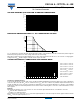
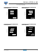
VOLTAGE DERATING AS A FUNCTION OF AMBIENT TEMPERATURE
ELECTRICAL CHARACTERISTICS I
max.
AS A FUNCTION OF VOLTAGE
I
max.
as stated in the electrical data and ordering information tables, is the maximum overload current that may flow through the
PTC when passing from the low ohmic to high ohmic state at rated voltage.
When other voltages are present after tripping, the I
max.
value can be derived from the above I
max.
as a function of voltage graph.
Voltages below V
rated
will allow higher overload currents to pass the PTC.
TYPICAL TRIP-TIME AS A FUNCTION OF TRIP CURRENT RATIO
Trip-time or switching time (t
s
)
To check the trip-time for a specific PTC, refer to the Electrical Data and Ordering Information tables for the value I
nt
. Divide the
overload or trip current by this I
nt
and you realize the factor I
t
/I
nt
. This rule is valid for any ambient temperature between 0 °C
and 70 °C. Adapt the correct non-trip current with the appropriate curve in the Current Deviation as a Function of the Ambient
Temperature graph. The relationship between the I
t
/I
nt
factor and the switching time is a function of the PTC diameter; see the
above graphs.
Example
What will be the trip-time at I
ol
=3AandT
amb
= 0 °C of a thermistor type 2381 661 54711; 2.5 Ω; Ø D
max.
= 8.5 mm:
I
nt
from the table: 470 mA at 25 °C
I
nt
: 470 x 1.12 = 526 mA (at 0 °C).
Overload current = 3 A; factor I
t
/I
nt
:
3
/
0.526
= 5.70. In the typical trip-time as a function of trip current ratio graph, at the 8.5 mm line
and I
t
/I
nt
= 5.70, the typical trip-time is 1.7 s.
120
100
40
80
60
0
- 25- 50 0 25 50 75 200
T
amb
(°C)
20
100 125 150 175
V
max.
(%)
100 120 150
200
100
150
80
I
max
(%)
7050400
V
rated
(%)
10
2
10
1
10
-1
t
s
12 4 6 8 10 12 14 16
I
t
/I
nt
(7)
(5)
(6)
(3)
(4)
(1)
(2)
Curve 1: Ø D
max.
= 20.5 mm
Curve 2: Ø D
max.
= 16.5 mm
Curve 3: Ø D
max.
= 12.5 mm
Curve 4: Ø D
max.
= 10.5 mm
Curve 5: Ø D
max.
=8.5mm
Curve 6: Ø D
max.
=7.0mm
Curve 7: Ø D
max.
=5.0mm
Measured in accordance
with “IEC 60738”.