
Datasheet

P6KE6.8A thru P6KE540A
www.vishay.com
Vishay General Semiconductor
Revision: 18-Sep-12
4
Document Number: 88369
For technical questions within your region: DiodesAmericas@vishay.com
, DiodesAsia@vishay.com, DiodesEurope@vishay.com
THIS DOCUMENT IS SUBJECT TO CHANGE WITHOUT NOTICE. THE PRODUCTS DESCRIBED HEREIN AND THIS DOCUMENT
ARE SUBJECT TO SPECIFIC DISCLAIMERS, SET FORTH AT www.vishay.com/doc?91000
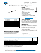
Fig. 5 - Power Derating Curve
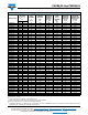
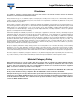
Fig. 6 - Maximum Non-Repetitive Forward Surge Current
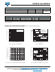
Fig. 7 - Typical Transient Thermal Impedance
6
5
4
3
2
1
0
0 25 50 75 100 125 150 175 200
L = 0.375" (9.5 mm)
Lead Lengths
P
D
- Power Dissipation (W)
T
L
- Lead Temperature (°C)
60 Hz
Resistive or
Inductive Load
200
100
50
10
1 5 10 50 100
I
FSM
-
Peak Forward Surge Current (A)
Number of Cycles at 60 Hz
Uni-Directional Only
T
J
= T
J
max.
8.3 ms Single Half Sine-Wave
t
p
- Pulse Duration (s)
Transient Thermal Impedance (°C/W)
10
100
1
0.1
0.001 0.01 0.1 1 10 100 1000