
Datasheet


NTCLE413
www.vishay.com
Vishay BCcomponents
Revision: 05-Mar-2019
1
Document Number: 29078
For technical questions, contact: nlr@vishay.com
THIS DOCUMENT IS SUBJECT TO CHANGE WITHOUT NOTICE. THE PRODUCTS DESCRIBED HEREIN AND THIS DOCUMENT
ARE SUBJECT TO SPECIFIC DISCLAIMERS, SET FORTH AT www.vishay.com/doc?91000
NTC Thermistors, Mini Epoxy PVC Twin Insulated Leads
DESIGN SUPPORT TOOLS AVAILABLE
FEATURES
• High adhesive strength between the PVC wire
and the encapsulating lacquer
• Accurate down to ± 0.3°C
• Small body of max. 3 mm for easy installation
• Material categorization:
for definitions of compliance please see
www.vishay.com/doc?99912
APPLICATIONS
• Temperature measurement, sensing, and control
• On battery packs, heat-sinks, tubing, enclosures, etc.
DESCRIPTION
These sensors consist of small NTC chip soldered between
stranded AWG #30, 105 °C resistant, PVC (UL2651).
Terminations are solder dipped. They are lacquered and
insulated with a black epoxy coating.
MARKING
Black lacquered body without additional mark
PACKAGING
SPQ: 125 items (for standard 40 mm lead wire length)
MOUNTING
By soldering the wire end, or crimping connector. The body
can be inserted in a tube, free in air, tape attached or glued.
Not intended for fluid immersed applications or continuous
contact with water. Not for potting in hard material or
over-molding applications. Consult Vishay for specific
application or mounting.
DESIGN-IN SUPPORT
• For complete curve computation, please visit:
www.vishay.com/thermistors/ntc-curve-list/
• Other R/T curves available on request
• The lead length can be customized
• Connectors can be added to the wire end
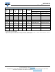
QUICK REFERENCE DATA
PARAMETER VALUE UNIT
Resistance value at 25 °C 4.7K to 100K
Tolerance on R
25
-value ± 1.0 to ± 5.0 %
B
25/85
-value 3435 to 4190 K
Tolerance on B
25/85
± 0.5 to ± 1.5 %
Operating temperature
range at zero dissipation
-40 to 105 °C
Maximum power
dissipation at 55 °C
100 mW
Accuracy of temperature
measurement (for 1 %
types)
± 0.5 between 0 and 40
± 1.0 between -40 and 80
°C
Dissipation factor
(in still air)
3mW/K
Response time
(in oil)
2.5 s
Climatic category
(LCT / UCT / days)
40 / 105 / 28
Minimum dielectric
withstanding voltage
between leads and
coated body
500 V
RMS
Weight (40 mm length) 0.2 g
3
3
D
D
3
D
3D Models
Design Tools
Available
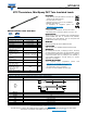
DIMENSIONS in millimeters
Electronic components of assessed quality measured in accordance with IEC 60539-1
Outline NTCLE413E2
Ø D max. 3.0
L 40 ± 5 (or refer to table SAP description)
L
1
max. 10
L
2
3 ± 1
W 2 (for information)
Ø d
1
0.3 ± 0.03
Ø d
2
1 (for information)
D
D
L
1
L
d
1
L
2
W
d
2