
Datasheet

NTCLE100E3
www.vishay.com
Vishay BCcomponents
Revision: 24-Aug-12
15
Document Number: 29049
For technical questions, contact: nlr@vishay.com
THIS DOCUMENT IS SUBJECT TO CHANGE WITHOUT NOTICE. THE PRODUCTS DESCRIBED HEREIN AND THIS DOCUMENT
ARE SUBJECT TO SPECIFIC DISCLAIMERS, SET FORTH AT www.vishay.com/doc?91000
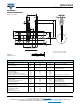
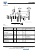
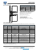
DIMENSIONS in millimeters
DETAILS SYMBOL DIMENSIONS NOMINAL TOLERANCE REMARKS
Body diameter
Lead diameter
Feed hole diameter
D
d
D
0
3.3
0.6
4.0
± 0.5
± 0.06
± 0.2
5 max. for 3.3 to 220
Lead to lead distance F 5.0
+ 0.6
- 0.1
Guaranteed between
component and tape
Distance component to tape centre
Component height
Component alignment
Distance top/bottom of components
Length of lacquer under the comp. bottom
H
H
0
H
1
h
H
3
20.0
16.0
10.0
0.0
± 2.0
± 0.5
max.
± 2.0
12 max. for 100 to 220
Not defined
Length of snipped lead L 11.0
max.
Pitch between thermistors
Feed hole pitch
Feed hole center to lead center
Component alignment
P
P
0
P
1
p
12.7
12.7
3.81
0.0
± 1.0
± 0.3
± 0.7
± 1.3
Cumulative pitch error
± 1 mm/20 pitches
guaranteed between
component and tape
Total thickness
Total tape thickness
T
t
3.0
0.9
max.
max.
4 max. for 3.3 to 220 with
cardboard tape 0.5 ± 0.1
Tape width
Hold down tape width
Hole position
Hold down tape position
W
W
0
W
1
W
2
18.0
5.0
9.0
1.5
± 1.0
- 0.5
± 0.3
± 0.5
± 1.0
None of the hold down tapes
may
cover the holes
T
ΔH
P
L
P
0
P
1
F
D
0
W
0
W
2
W
W
1
H
0
H
Δp
d
D
H
3
H
1
t
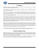
Taped according to IEC 60286-2
(cover tape may differ from shown)
2E pitch
NTCLE100E3...T2
Thermistors on tape